- Home
- Forums
- Ride Reports
- MotoBikes
- Restorations
- Wrenching
- 1963 BMW R69s
- 1969 BMW R60/2
- 1978 Yamaha 125
- 1979 KZ1300
- 1979 Kz1300 - Bob's Beauty
- 1981 CBX SuperSport
- 1981 Kz1300 Model A3 - Chocolatie
- 1984 Ford F250 XL
- 1987 ATK
- 1987 MowieMowie
- 1987 RotoTiller
- 1988 Honda Accord Lxi
- 1990 BMW RT100 - Barrie
- 1991 Harley Davidson FLHTCU
- 1992 Johnnie Deere
- 2000 YZ426
- 2002 Dodge Ram
- 2006 Carson RacerX Trailer
- 2006 Host Camper
- 2006 KrZy8
- 2007 Wabs
- 2012 KTM 690R
- 2013 Naomi - FJR 1300
- 2014-08-01 Air Compressor - Sears
- 2017 Kioti
- 2018 Toy Hauler
- 2020 Honda Fit
- 2021 Miscellaneous
- 2024 Log Splitter
- 2024 NeoDyne MC Lift
- 2050 test
- Lil Trlr
- Eats
- RIP
- PC Not
- Cages
- Test
- FJRF Best
- For Sale
Candy Butt Association
World's Wimpiest Riders
You are here
2021-05-02 CBX Alternator 19vdc

Forums:
2021-05-02 19 Volts from Tim's CBX Alternator
Months ago purchased an alternator from Tims CBX. It had high outuput, almost 17 Vdc. Called Bill at Tims (new owner is Bill)
who said send it back. I did, the alternator was refurbished with a new regulator, and the unit shipped back.
Then I got busy working away from home and the alternator sat in the box.
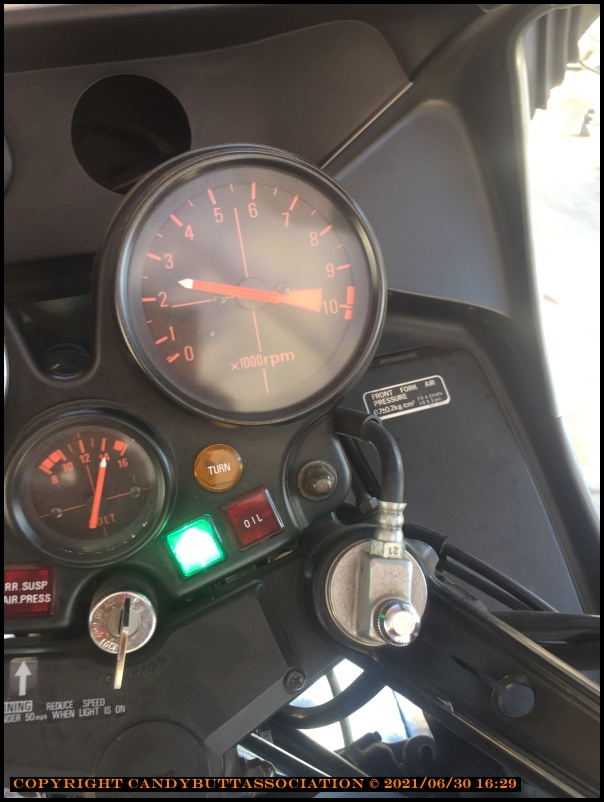
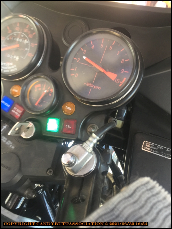
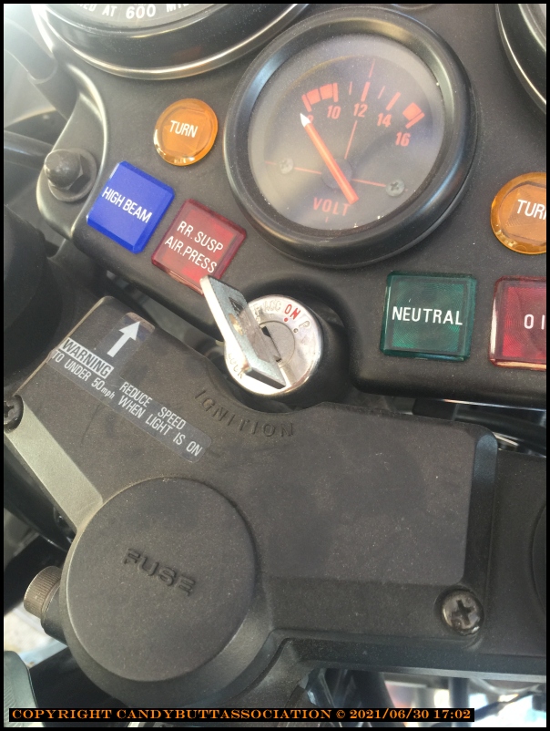
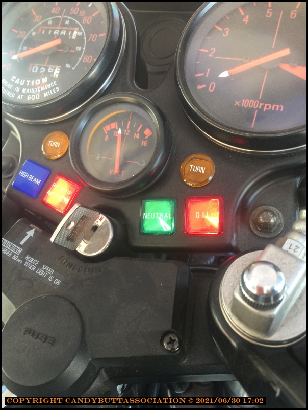
Yesterday, installed the alternator and CRAPOLA the output is higher than before, almost 19 volts!
Alternator adapter plate and OEM rubber dampner.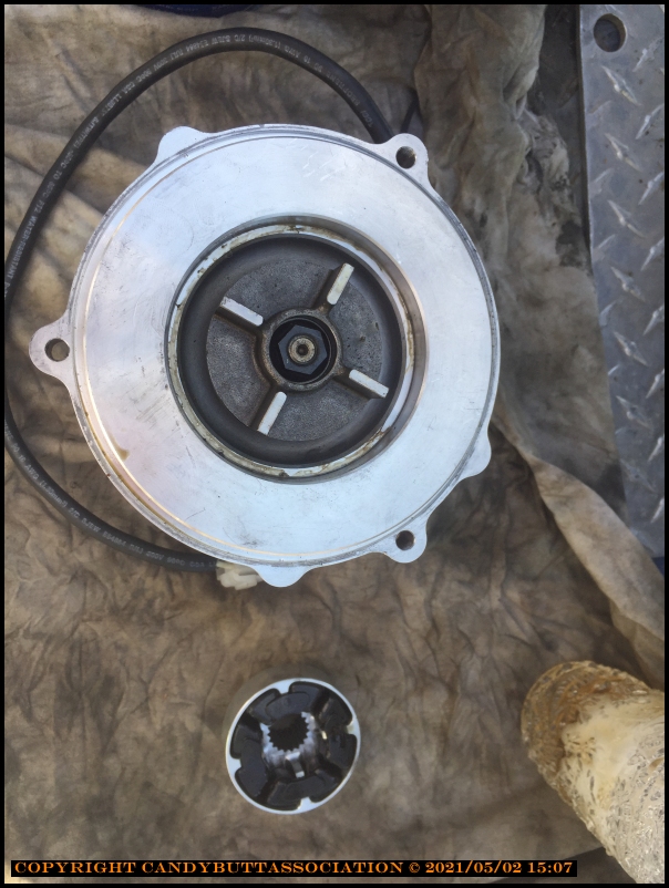
Fits in here.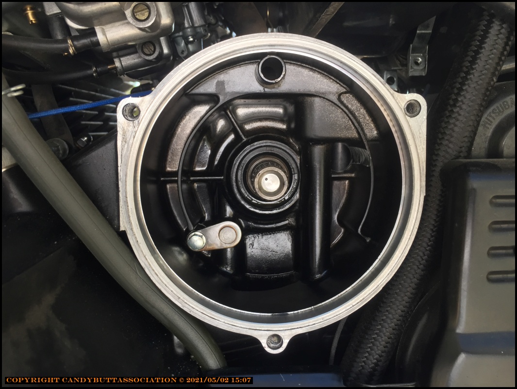
Nice clean engine interior!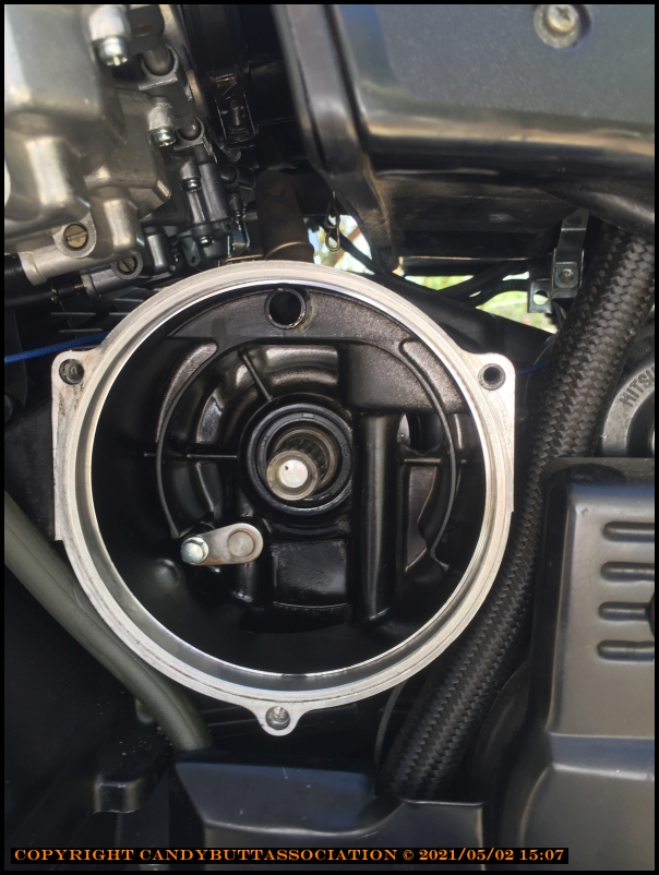
The repair shop Bill uses..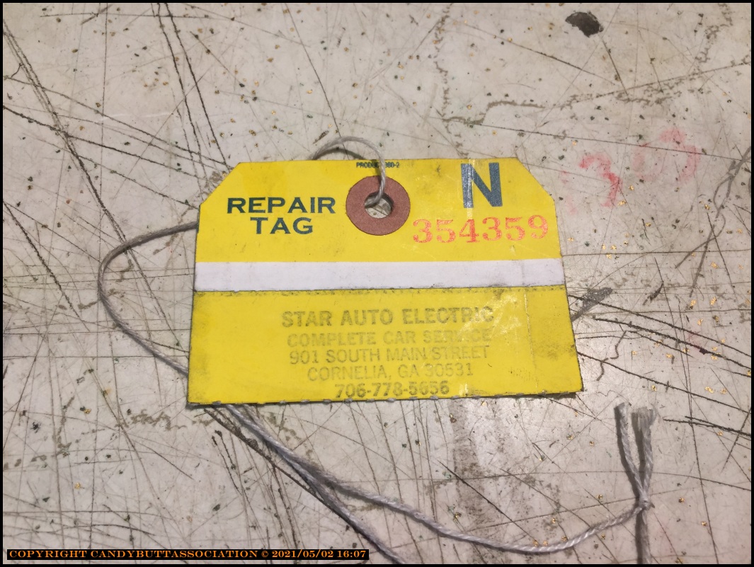
So it's time to remove and ship once again.. Bill said he would send me a completly different unit this time.. but it will have to wait a bit as Bill is riding a 1,000 mile dirt only ride.
He leaves May 6th and returns May 16th.
Tims CBX attn Bill
191 Roberts Way
Cornelia, GA 30531
Theme by Danetsoft and Danang Probo Sayekti inspired by Maksimer
2021-06-03 - The Saga Continues
Bill from Tim's CBX left voicemail, please call.
Long of short, Bill's alternator shop, Star Auto Electric, found nothing wrong with alternator/rectifer/regulator ZX7 unit. They only replaced the regulator as cheap insurance. Star says the sent back alternator was just fine.
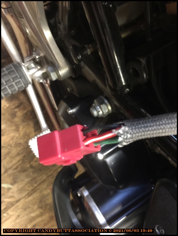
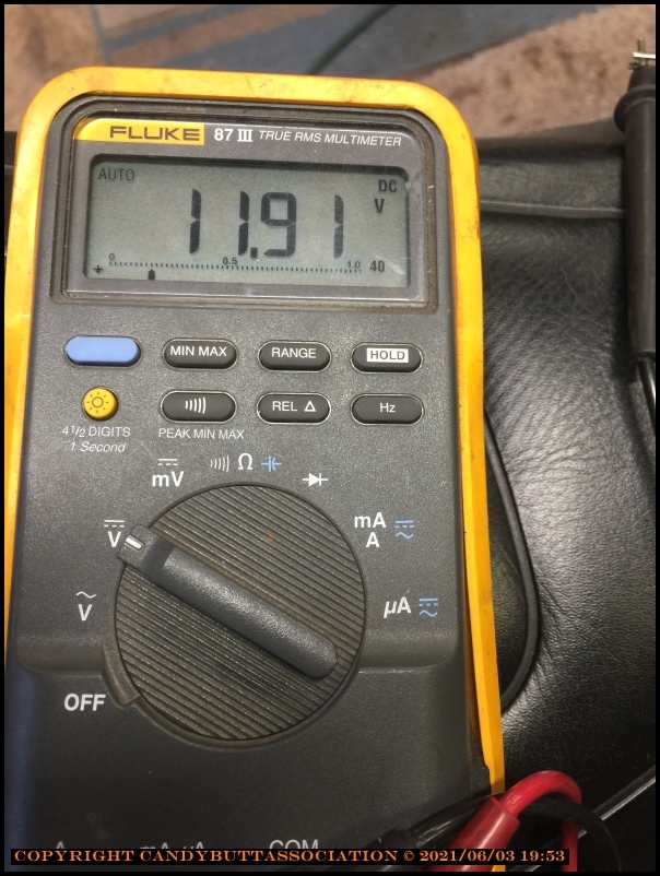
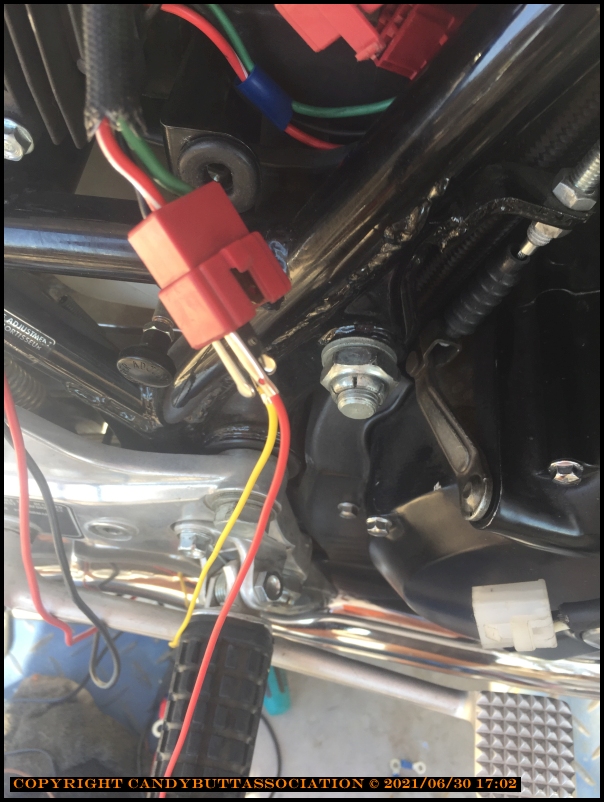
Star recommended via Bill that I measure the black lead to ground, should be 4 - 9 Vdc.
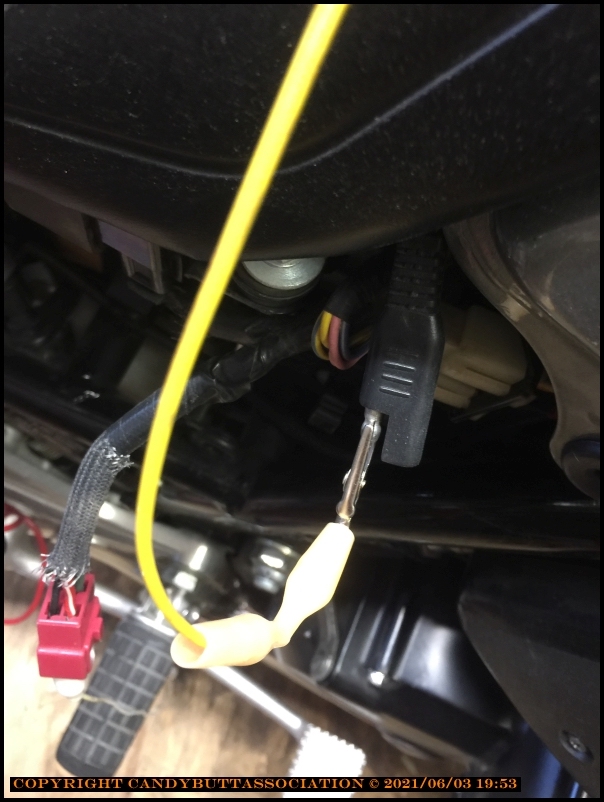
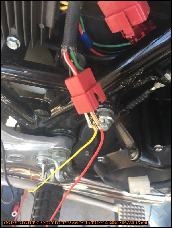
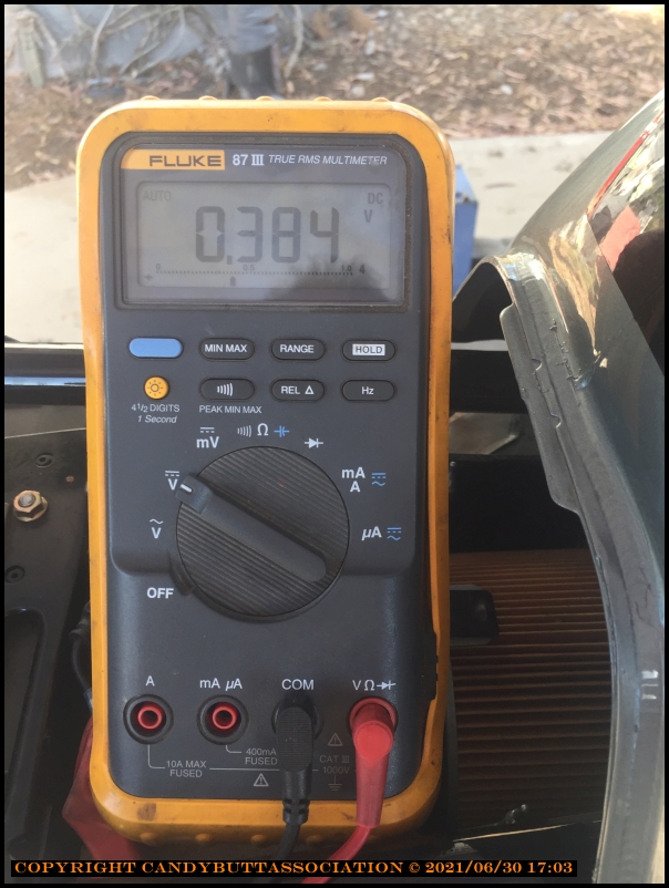
This is the black wire.
Ready to measure.
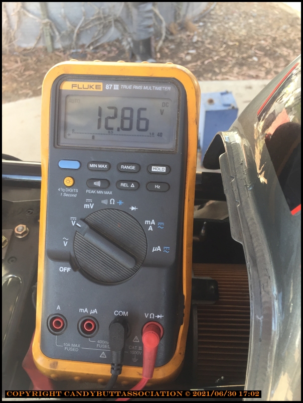
Certainly not 4 - 9 vdc..
x
x
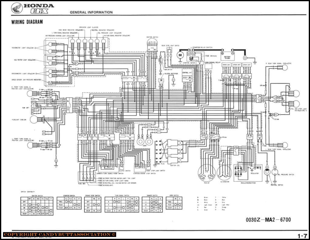
2021-06-04 Cbx Wiring Schematic Diagram
More CBX Alternator Info
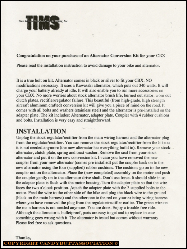
Install Directions
Close up view.
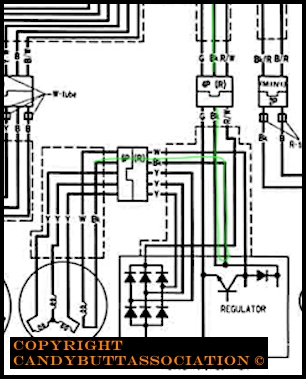
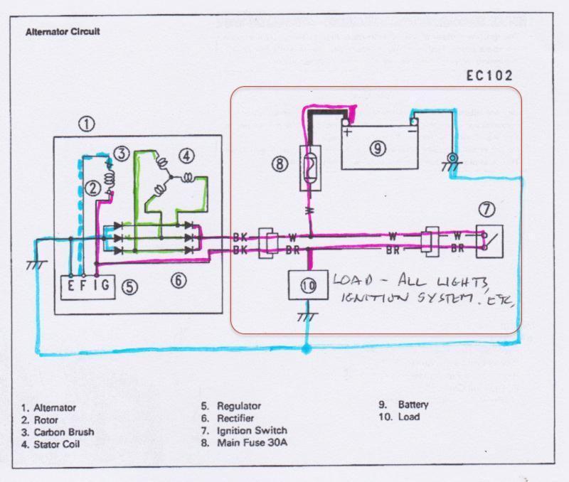
Tracng the black lead indicated by thin green line.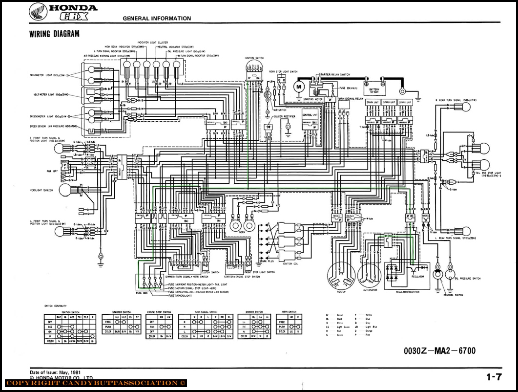
OEM schematic.
x
2021-06-18 Brian and Jason join the Fray
Hi Brian and Jason,
Thanks for following up! Here’s what I’ve learned so far:
Here’s the Zx7 schematic: (Oem schematic here)
Plan of Action
Looking at the schematic, is this how it works?
Dang, so much to learn!
Thanks for helping guys, free beer on me next time!
2021-06-18 Tim's CBX ZX7 Alternator Info
Clicky for PDF file, Alternator section of Kawi Zx7 manual
Clicky Here for Tims CBX Install directions
2021-06-18 Testing Alternator
2021-06-20 Vdc & Resistance Measurements
So then, I ASSume...
. All grounds are good, battery to frame, including alternator bolts
. No serious voltage drops due to poor grounds
. The R/W wire is providing +12V to regulator
. Alt is grounding via 3 mounting bolts
. Rotor field current is Black wire (11.7 vdc when battery is at 12.18 vdc)
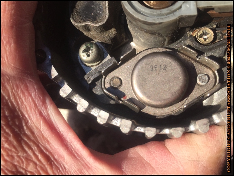
2021-06-21 CBX Stator Test
So then, more info. From the FSM, it appears the CBX OEM stator circuit might be different than the Zx7 aftermarket kit? Under 'Stator Testing' it specifically mentions output voltages of 8 - 10 vdc Which I'm guessing isn't in play on the Zx7 kit alternator? It appears the OEM alt has two zener diodes that I bet are providing the 8-10 vdc rotor field current? Here's the CBX schematic Zx7 schematic Image
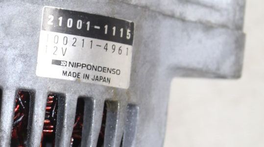
2021-06-21 Nippon Denso Zx7r Alternator Info and Internal Pics
Nippon Denso 21001-1115
Pic with cover off
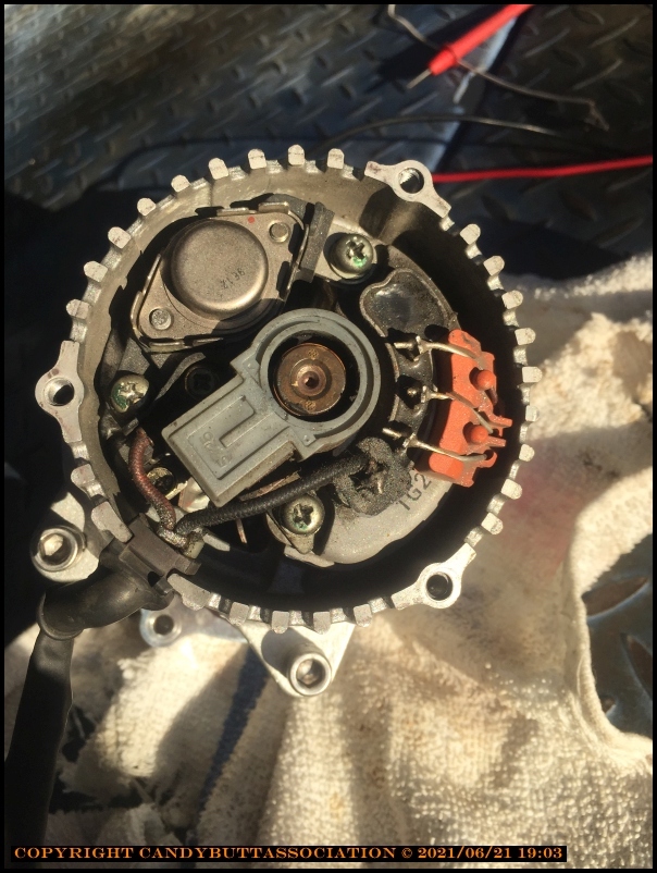
Transistor part number
Part Number from eBay pic
2021-06-22 Bench Testing
Ok then, status update.

Decided to bench test the alternator. Found battery, fuse, switch, H4 halogen for load, wired everything up, monitored volts with Fluke 87 and current with clamp on DC ammeter. Spun with two different drill motors; battery Makita and higher speed 1940's vintage motor used for drilling pop rivet holes in WWII aircraft at Douglas aircraft.
Before bench testing, inspected wiring and found the added wiring, which connects stub alt wires to new connector, wasn't crimped or soldered. Twisted, taped, and heat shrunk. Horrible horrible horrible. So soldered, heat shrunk each wire then heat shrunk outer sheathing.
It *apparently* bench tests SAT.. but I'm not sure what the max rpm from either motor is? Sure can't match CBX rpm capabilities meaning the bench test may or may not be a legit test... Thinking that if, say max drill motor rpm is 3k, equaling ~14.x volts, what happens at 8k rpm or higher? Voltage stay at 14.x or climb right back up?
Excited to have found the output wires merely twisted together, had high expectations it would now work great on the bike..
Installed kit alternator on bike, instant 17+ volts.
Lastly, installed stock alternator, worked perfect.
Next steps (Test CBX wiring per McaTrophy suggestion
. Measure R/W to Blk with battery disconnected
. Reinstall ZX-7R alternator, run output direct to battery, e.g. bypass wiring harness. Run alt field core wire direct from battery through fuse and manual switch
Thoughts, Ideas? Suggestions? Ridicule?
Don
2021-06-22 Email to Tech
Wow! Thanks for responding, Jesus. I greatly appreciate your help. :)
Confirmed.
. Reinstall ZX-7R alternator, run output direct to battery, e.g. bypass wiring harness. Run alt field core wire direct from battery through fuse and manual switch
2021-06-30 Test TimsCbx Alternator On Bike - Bypass OEM wiring
Edit
2021-06-30
Testing TimsCBX Alternator on Bike
Bypassing OEM harness
Decided to try suggestion of measuring OEM R/W to BK, battery disconnected. This should determine
if a voltage drop exists in the circuit as shown below.
Thinking that should resistance in that circuit be high, resulting in voltage drops, the alternator is 'fooled'
into sensing a low battery condition and going to full output.
Total lead resistance.
Lead resistance zeroed out.
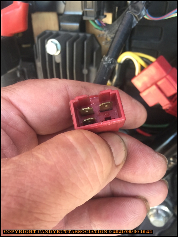
Ohms x1 scale acrss R/W and BLK, battery disconnected, key On.
Resultant resistance = good.

Used Dremel and wire brush to clean up already clean contacts.
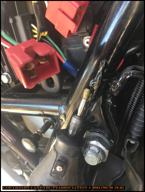
Squeeky clean
Alternator output at:
2.5k rpm - NOT good.
Onward to test #2.
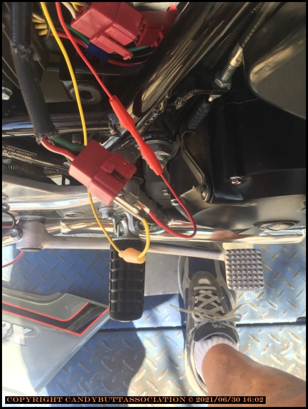
Bypass OEM wiring completely.
1. Battery plus directly to RR 'I' per pic below .
2. RR output direct to battery via BK/W, see pic below
17+ vdc not good
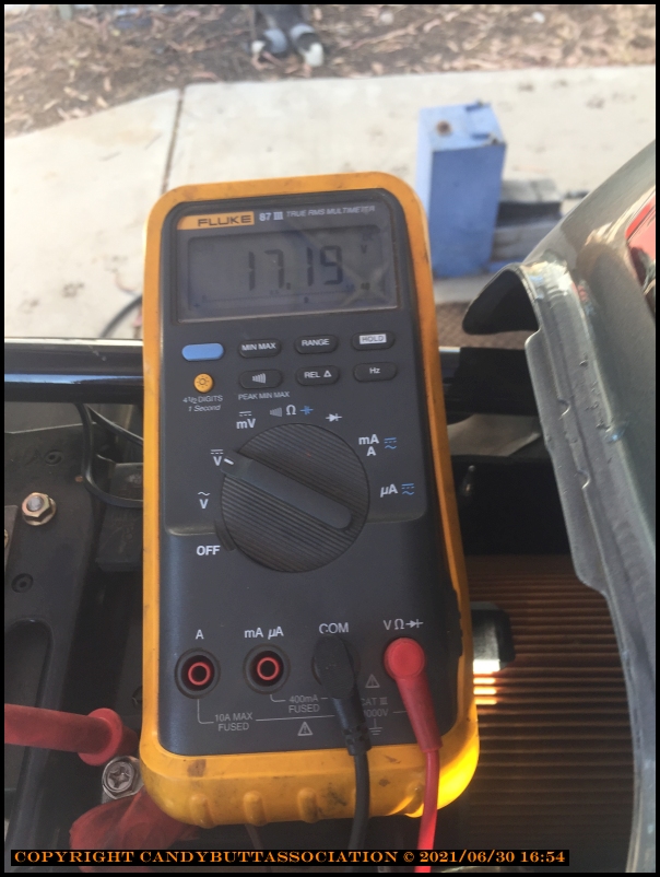
At 2.5k rpm
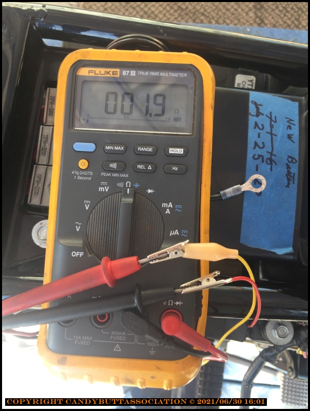
Test 3
Measure VDC at R/W to BK
Key off
Connection
Same VDC as when measured directly across battery terminals
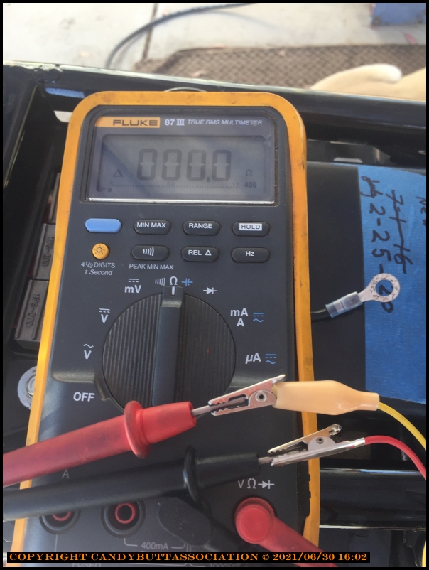
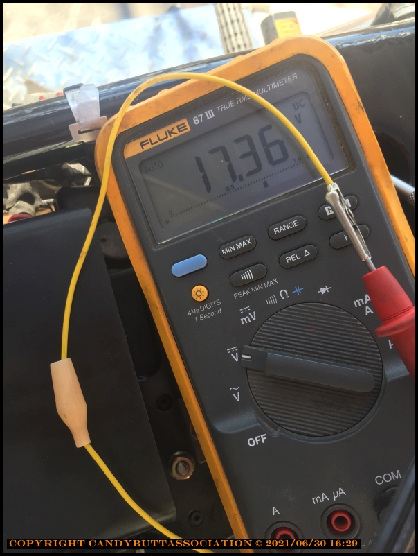
Key on
Same connection R/W and BK
VDC drop
What does all this prove? Here's my guess.
Next Steps
The R/W isn't going to the regulator, it is the alternator's rectified output, equivalent to the upper BK connecting to W in your very first picture. The lower BK, going to BR in your first picture should connect to the Bk (Black) on the CBX connector.
If you have got it connected correctly, please read on.
Measuring at the new alternator, expect a low reading (I'd guess a few ohms) from the lower BK to its frame, and extremely high on the upper BK to frame - if your meter has a diode setting, you may get a diode indication with the meter's negative lead to the upper BK wire and positive lead to frame. With the leads the other way round, it should read very high resistance.
CORRECTION: You should get high readings from both BK connections to alternator frame (some idiot forgot about the regulator mechanism). However, if you have a diode setting on your meter, you should get a reading on the alternator output connection (upper BK) to alternator frame with the positive meter lead to the frame. You may also get a diode reading on the field connection, depending on the regulator circuit, but if you do, I would expect the reading to be lower on the field connection (most meters would give a reading of about 0.6, one diode in the circuit), and a higher reading on the output (two diodes in series, a reading of about 1.2).
So, with the meter set to Diode, the positive lead to the alternator frame, the output BK should always have a diode reading, I would expect about 1.2, the field may read very high, but if it does indicate, expect about 0.6. Sorry for the confusion.
It is difficult to measure resistance below 1 ohm with a normal multimeter. The slightest bad contact will introduce errors.
The technique I generally use is to use pointed probes, not clips if I can avoid them. Twist the plugs of the leads in the meter a few times to ensure good metal to metal contact. Push one probe fairly hard onto one of the locations, then push the other probe onto the same location, the meter will ideally read zero, but may read up to 0.1 ohms. Waggle the probes a bit, make sure the reading is stable. Now move one of the probes to the other location, press and waggle, take the reading when you are sure it is stable. If you must use clips, use your fingers to crush the jaws tightly on whatever you are clipping to.
Having said that (and hoping I'm not insulted your abilities), a comment on your results.
I'm assuming the colours are from the original CBX wiring diagram (I have found two, 79-80 and 81-82). The Green is connected to the frame, Black is the switched ignition, Red/White the alternator's rectified output.
The resistance measurements to battery ground - the Green 0.2 ohms is higher than I would expect, but see my comments about the difficulties of measuring low resistance. The Black 0.5 ohms to ground isn't important in this quest. It is the load on the ignition circuit (mostly the lamps since any electronics won't draw any current at the meter's excitation voltage).
A more significant resistance reading would be from the Black to the Red/White. To do this, disconnect one of the battery terminals, then turn on the ignition switch. This includes the path I showed in dark blue in my last picture in my post above.
reserved for later
x
2021-07-15 Alternator works on Jason Len's CBX
My bud Jason Len graciously allowed me to use his 1979 CBX as a test mule. I took VDC measurements across his R/W, Green, and Black to ground and the resultant voltage drops of each wire compared to battery voltage was very very close to mine. <post data table later>.
Connected my alternator to his wiring harness, spun alternator with drill motor, resultant voltge ~12.6 volts with a battery voltage of 12.3 IIRC <check later>.
So apparently, it's not the alternator after all.
More later
2022-12-01 OverCharging more info