- Home
- Forums
- Ride Reports
- MotoBikes
- Restorations
- Wrenching
- 1963 BMW R69s
- 1969 BMW R60/2
- 1978 Yamaha 125
- 1979 KZ1300
- 1979 Kz1300 - Bob's Beauty
- 1981 CBX SuperSport
- 1981 Kz1300 Model A3 - Chocolatie
- 1984 Ford F250 XL
- 1987 ATK
- 1987 MowieMowie
- 1987 RotoTiller
- 1988 Honda Accord Lxi
- 1990 BMW RT100 - Barrie
- 1991 Harley Davidson FLHTCU
- 1992 Johnnie Deere
- 2000 YZ426
- 2002 Dodge Ram
- 2006 Carson RacerX Trailer
- 2006 Host Camper
- 2006 KrZy8
- 2007 Wabs
- 2012 KTM 690R
- 2013 Naomi - FJR 1300
- 2014-08-01 Air Compressor - Sears
- 2017 Kioti
- 2018 Toy Hauler
- 2020 Honda Fit
- 2021 Miscellaneous
- 2024 Log Splitter
- 2024 NeoDyne MC Lift
- 2050 test
- Lil Trlr
- Eats
- RIP
- PC Not
- Cages
- Test
- FJRF Best
- For Sale
Candy Butt Association
World's Wimpiest Riders
You are here
1987 ATK

Forums:
.. restoring an 1987 ATK
3 4 or so years ago, on the way to SX races in San Francisco, my buds unmercifully harassed me about failing to complete the ATK project.
"Tell me again how you have a complete rolling chassis and it STILL ain't running?" asked Jack. "Hell it's only been apart for 7 or so years" I retorted. Besides, I'm a busy MoFo".
That's when Jack chimed in; "I'll stuff that engine back in the frame, wire it up with Baja Designs components, fix all the broken crap for you. Toss me a 1,000 bill and I'll make it happen, parts cost only, free labor." 
"I'll ask you again tomorrow, Jack, when you aint been drinking" sez I.
Roll onto tomorrow, and Jack is sticking by his story.
So, after spending some time under Jack's tutelage, the ATK is ready to make the journey back home. it should be back sometime August 2010.
The only problem is a nagging ignition issue. After running for a bit, it loses spark. I just happen to have some spare parts laying around the house (I raced MX on this bike 87-91) so I can throw them on shot gun style and see what happens. IIRC I have ign coil, rotor, stator, cdi. But that motor always had weak ignition - although it would always run.
Researching the net, it *appears* that CDI modules are no longer available for 87 and earlier XR's. I hate to think about buying an 88 or newer just for parts, but I can and will if needed..
The bike, at my buddies house.
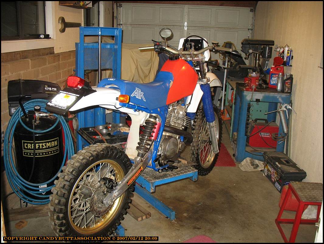
Another view..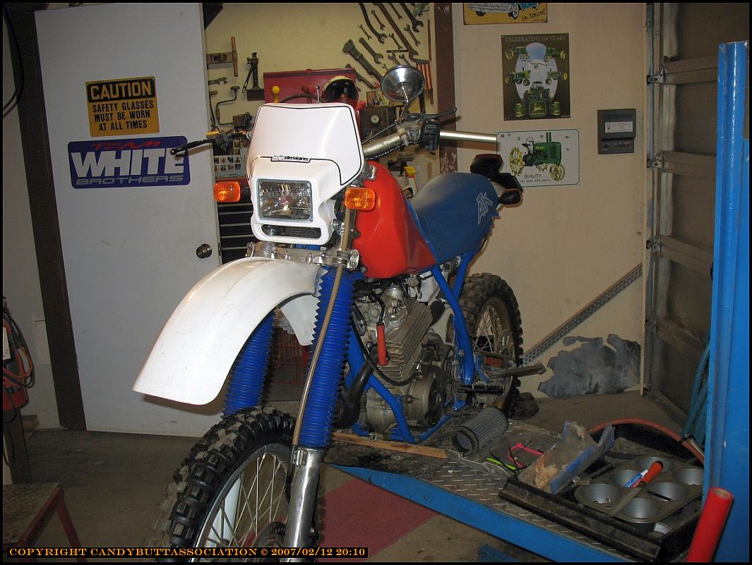
Over last weekend, got the mighty ATK running.. new secondary coil, from the parts bin. Then, worked on detail stuff..
making hose clamps the right size, found some OEM Honda brake pads for the front (nothing there when bike sent/received).
The next step is to buy control cables..
- Throttle
- De-compression
Apparent sources are flanders.com, motionpro.com.
The local guy wanted 50 bucks per cable.. so I balked.
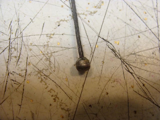
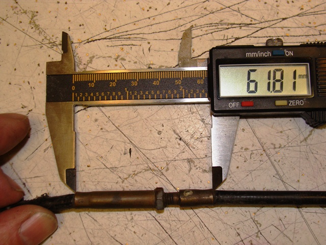
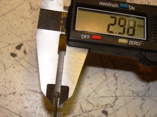
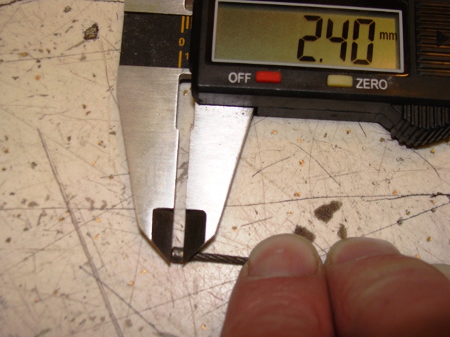
It turns out MotionPro can make cables.. so I took some pix of the dimensions -
Inner cable OD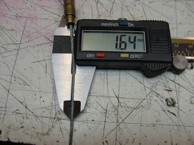 |
Throttle end. |
Trottle end width. |
|
Throttle end height. |
Throttle end ferrule. Both ends look the same. |
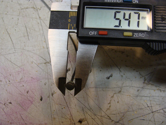
Throttle ferrule small diameter
|
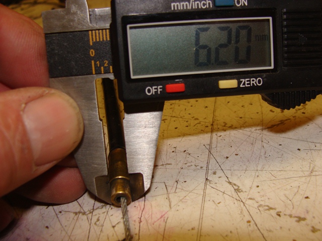
Throttle ferrule big diameter.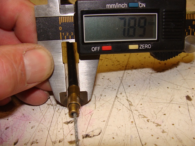 |
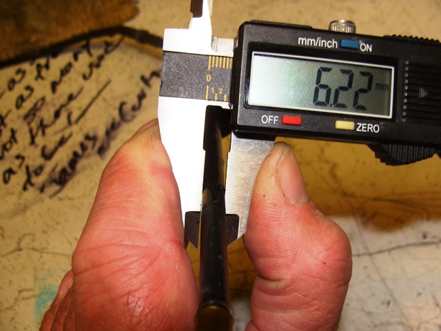
Outer sheath OD.
|
Adjuster length. Note - this is the correct setting for the bike.
|
|
Carb end Inner diameter.
|
Carb end OD. |
Carb end boot. |
|
Carb end. |
Carb end width. |
Carb end height.
|
Cable free play. Note that it would be tad longer because the adjuster is taking up some slack. See pix above for adjuster. |
Overall outer sheath length. |


hmmm, this looks good <clicky>
and <clicky>
2010-01-20 Update
Woot Woot!
- Adjusted valves (they were tight)
- Completed front brake cable alignment
- Found several companies offering throttle/cables that should work (see above)
Here's some updated pix..
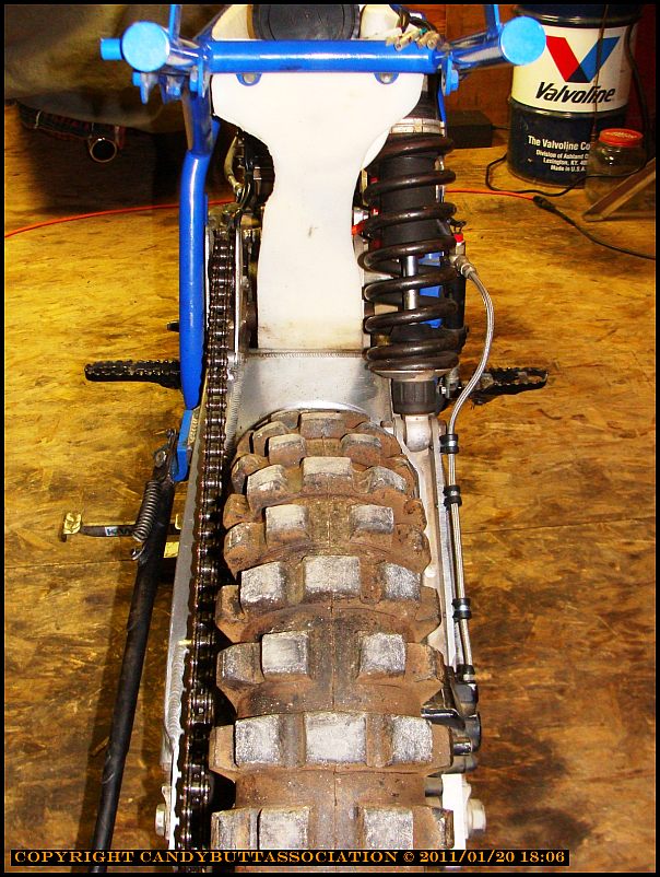
CC breather fixed and aligned, air filter realigned.
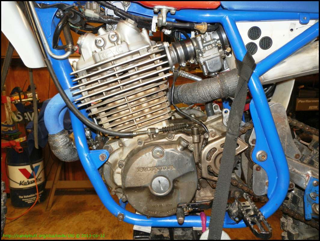
Skinny Minnie. No stinking radiators, no water, air cooled nirvana, baby!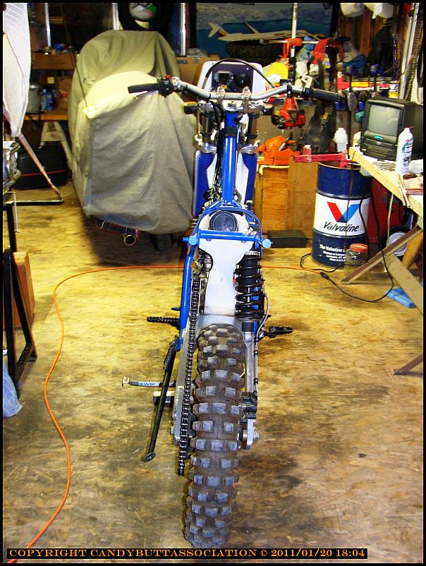
Problem - CR250 brake/master cylinder assembly on Easton Flex bars (remember them?) in conjunction with Magura 314 throttle assembly has all sorts of issues. In this pix, the throttle tube is cut down by approx 1" - see the compressed grip - and it just ain't enough territory to hang on to. I need to find a throttle assembly with a smaller OD to clear the Honda brake lever adjusting nut.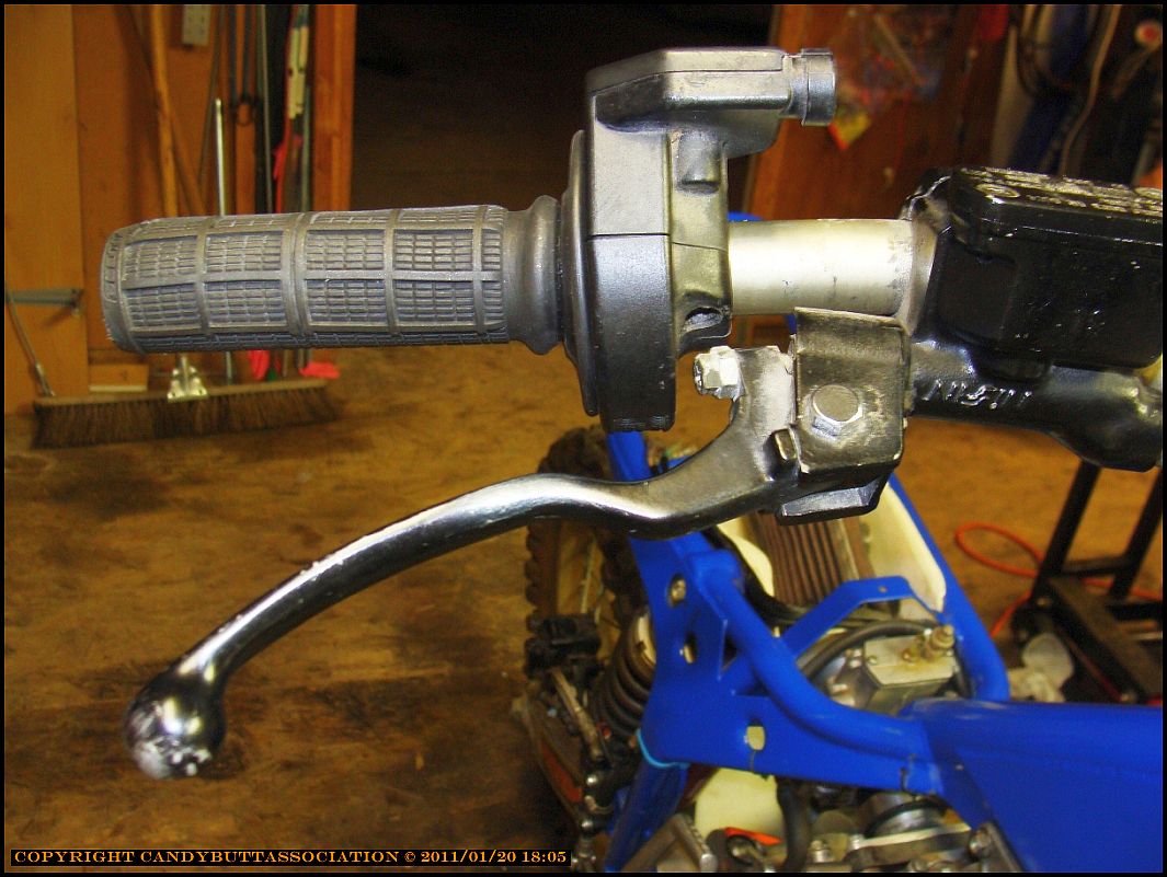
More pix of the project bike..
What the deer sees.
How old school is this? I'm having a blast working on this bike.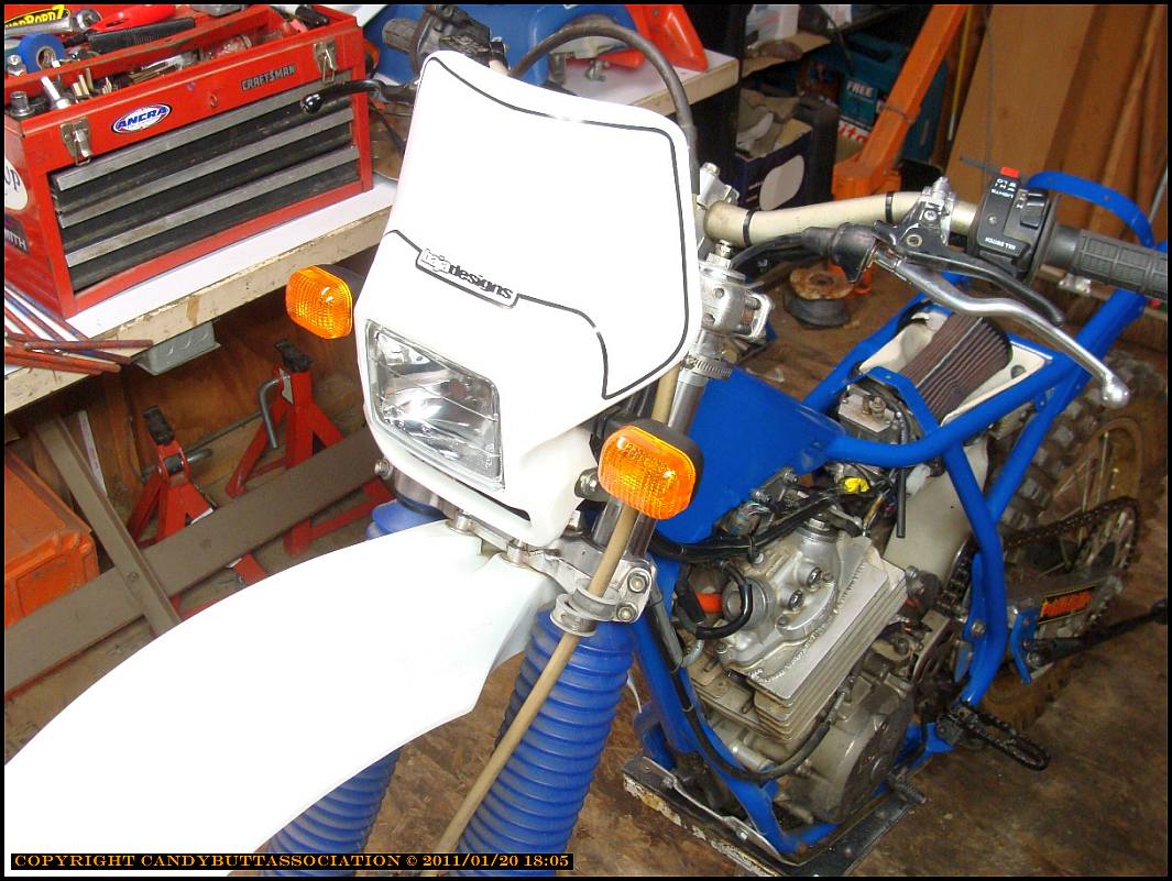
Is the AdvRider.com front page material?
The ATK anti-torque system. Pulling in a straight line eliminates suspension compression under acceleration. Take your bike, nose the front tire against a wall, apply throttle and a little clutch. The bike will squat. The ATK remains level, allowing maximum speed in the whoopage.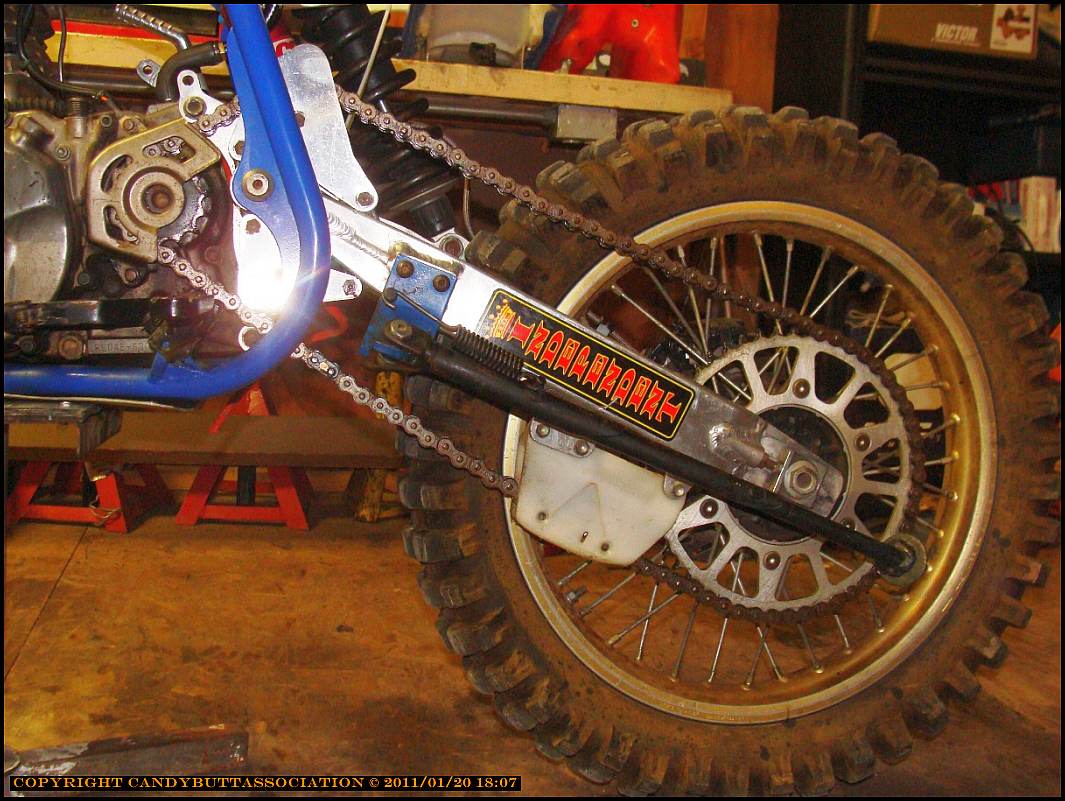
Ruh Roh Rollie - the crankcase bolt access cap came off hard. Wonder if this part is still available? Fortunately, I had a spare.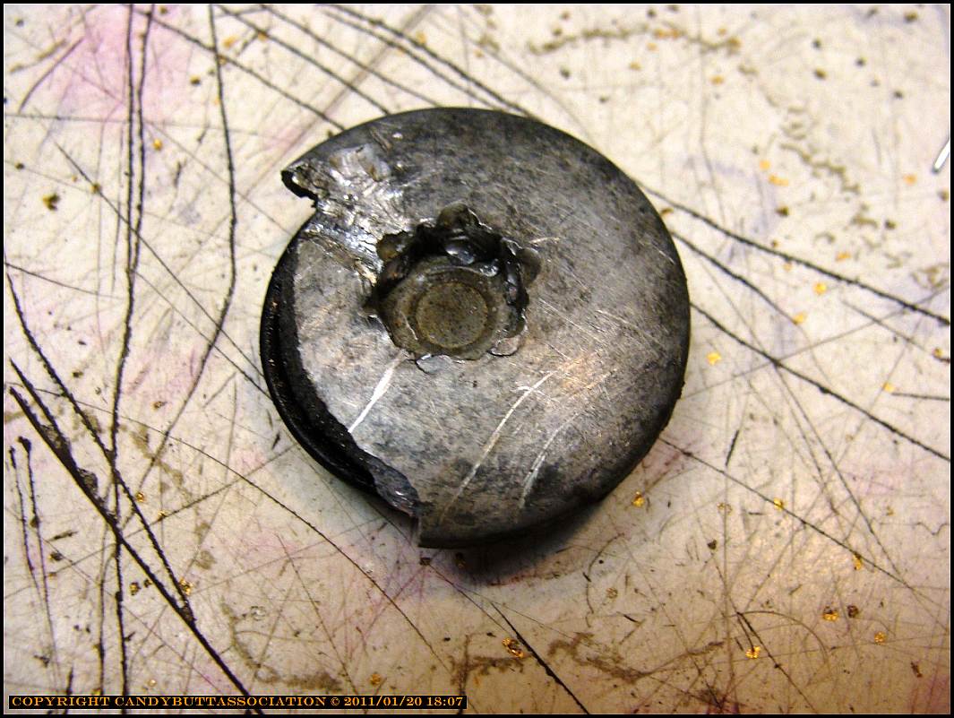

And I need some caps for these thingies..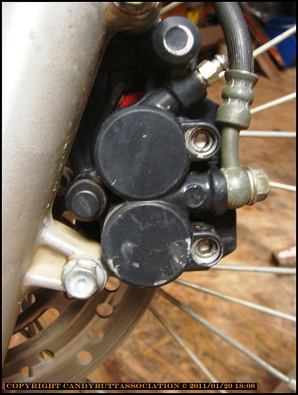
Monday 1/24/2011
Spent most of Sunday working on the ATK.
- Rerouted the wiring harness from backbone left side to right side. It was blocking access to the choke lever.
- Hogged out airbox filter hole at carb side to allow the clamp better purchase on carb throat/K&N air filter.
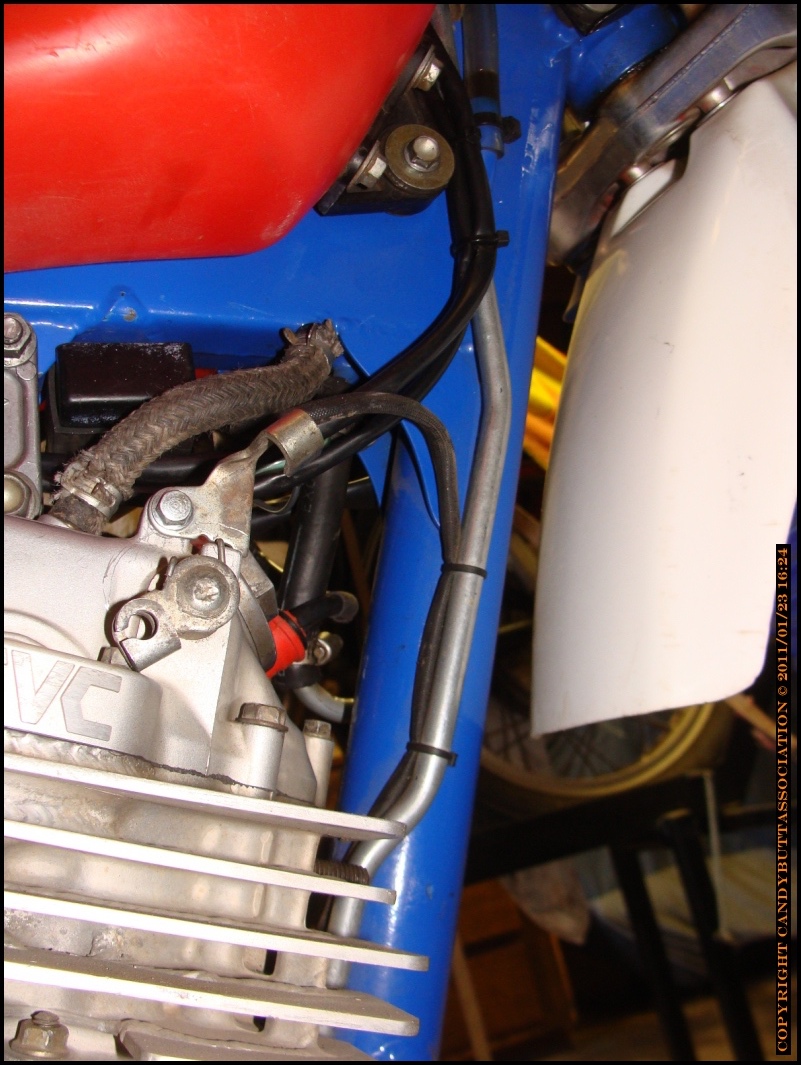
- Wirebrushed then painted header in hi heat blue. It looks kewl.
- Removed oil line running from valve cover to pump to remove header.
- Color wrapped various connections for easy ID of which wire goes where.
- Lubed and adjusted clutch cable.
2011-01-26 First Ride Today
..but first, some previous work to catch up on -
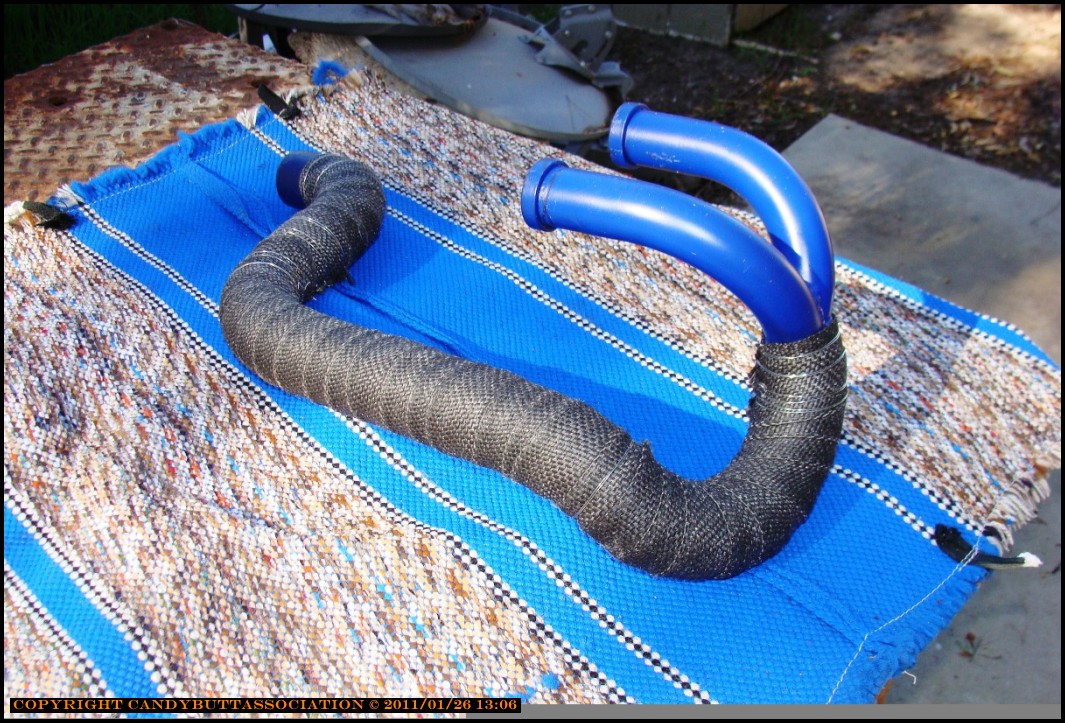
Exhaust header, wire brushed, cleaned with thinner and ready for paint.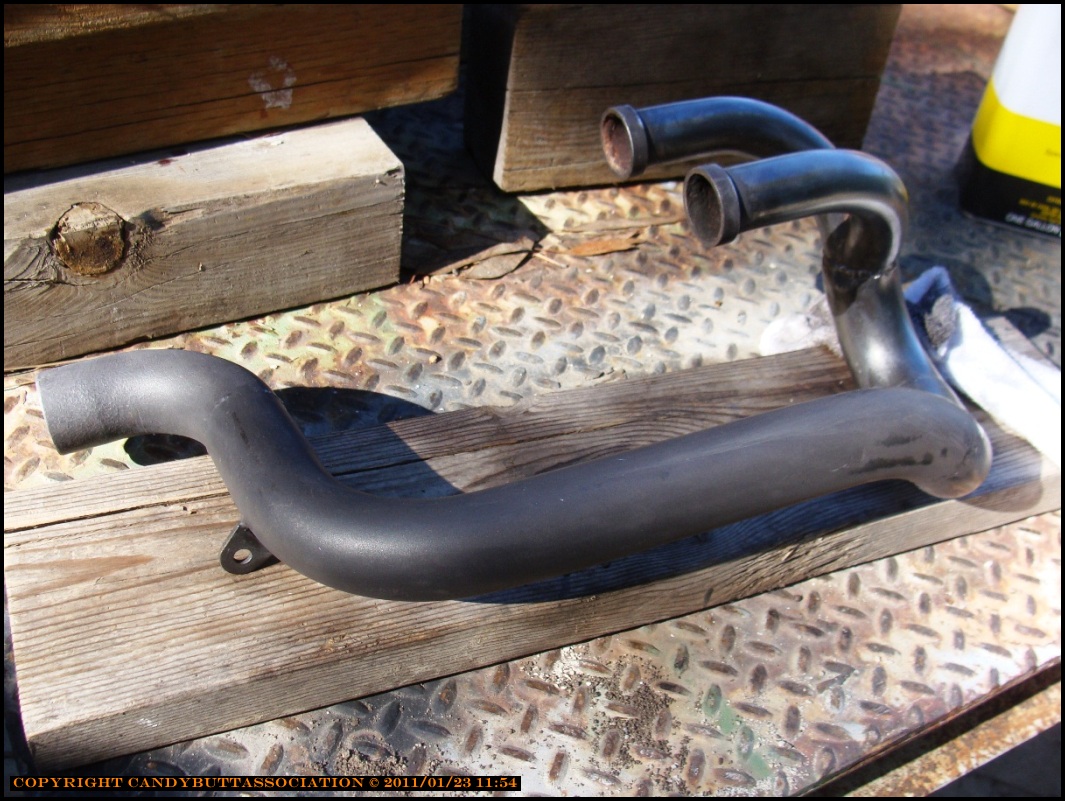
Wrapped and painted with hi-heat high dollar paint..
Re-routing of wire looms and control cables. 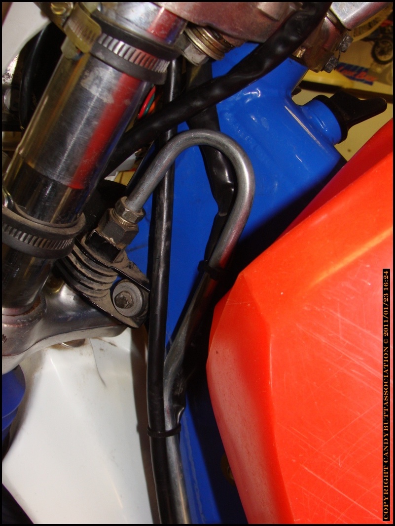


Getting there! Ready for the first ride,sans seat.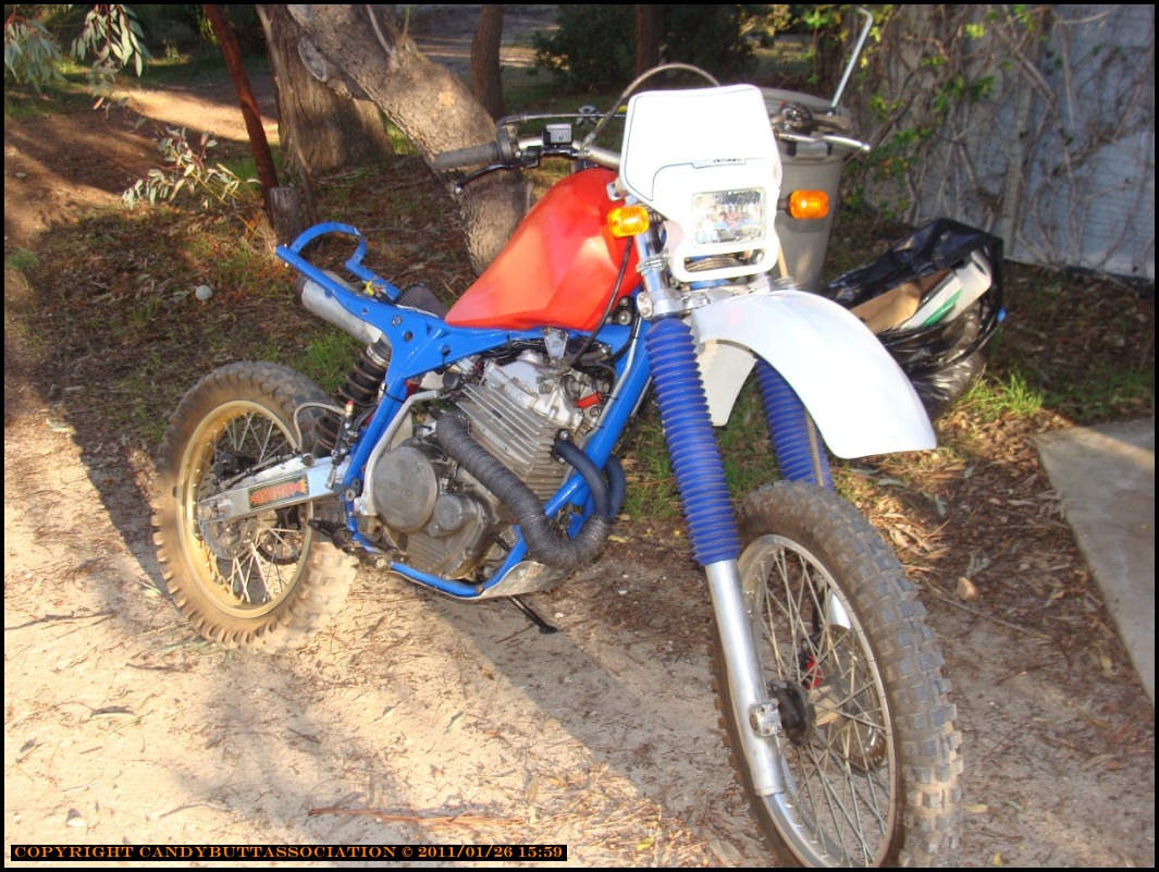
2011-01-30 A rainy day
Last day of the first month of 2011, got to say I've been wrenching more this month than in a long, long time. Kinda fun except my hands hurt. And back. And feet. But what the fuck, this is really kind of fun. So I ordered up this really cool Moose racing clutch lever/hot start (for me, decomp lever) and bummer what a fooked up idea this turned out to be. I completely missed the boat when at Hidden Power Cycle Clinic - forgot all about the the switch assembly. Sigh.
Here you can see the problem.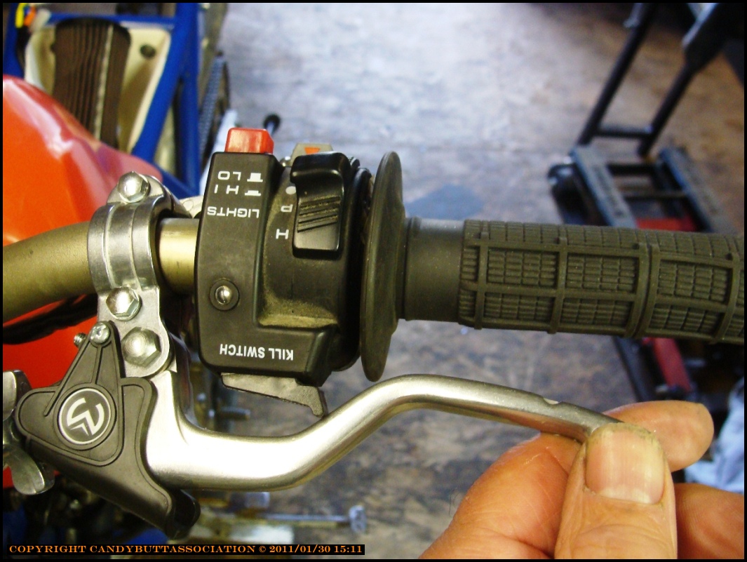
I mean, really, how bad is this? Both front and rear don't fit. Where was my brain?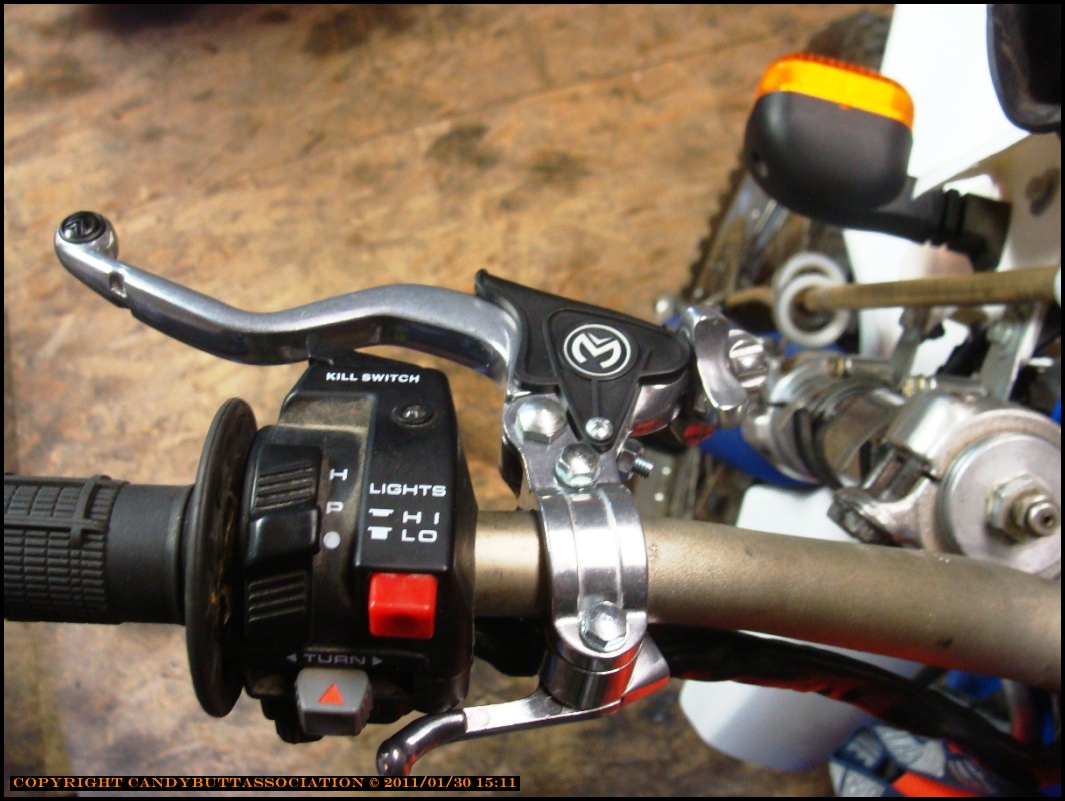
Oh, well, live and learn. Moose also carries dual purpose levers that carry the hot start (decomp) on the top side. I measured the cable holes, where the cable end fits into the lever, and the current decomp lever had the same size, but was not deep enough. Not sure if this will ever work, and I have some time this afternoon, so why not play a bit and see what works with hardware on hand?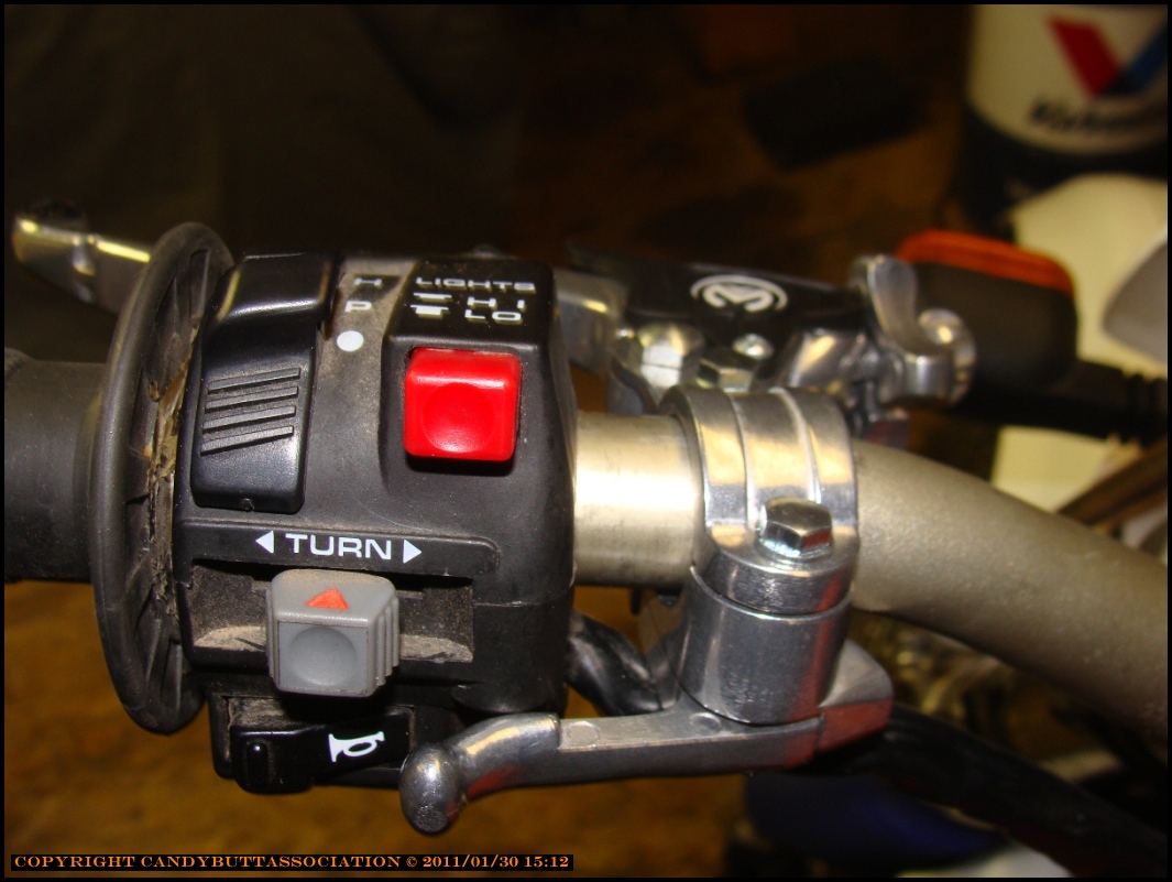
Taking a break from the lever project, I saw that K&N makes a filter that has slight downward angle to it. As seen in other pix, my current filter angle isn't really right for the airbox and will hit seat bottom. What's more, it does not really fit well onto the carb bell. Not good enough at least.. I needed the bell diameter to order the new filter.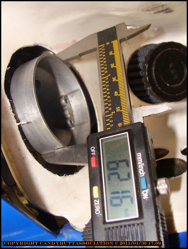
Just saw this tonight, and I'm somewhat concerned. This is the aluminum intake manifold mating the Mikuni TM38 carb to the XR600 engine. I have questions about the epoxy - is it strong enough? Will it withstand heat cycles and vibration? Why is it there? Seems a good weld would not need additonal sealer?
I sent email to my mechanial engineer bud, I'll trust his judgement - he knows his stuff.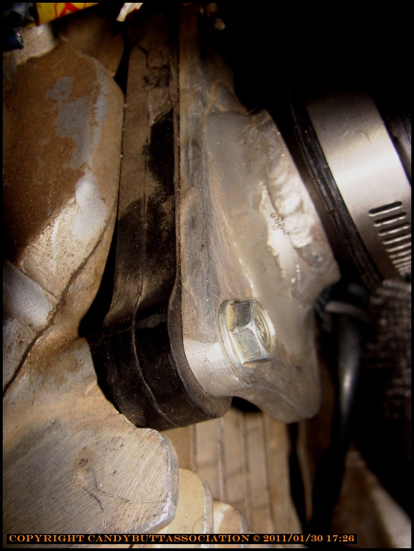
Another view of the epoxy job.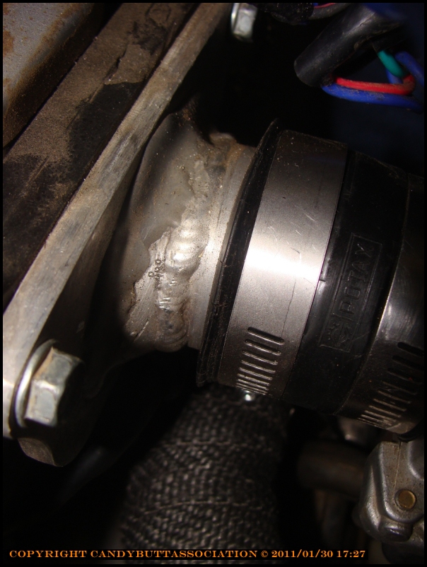
Also, did the following
- Moved the exhaust pipe to the outside of the frame to allow rear wheel clearance.
- Found AmericanDirtBike - they have some parts, including the ATK chain idlers..
- Found ThumperTalk - it appears my ATK might be very rare? ($$$$) LOL.
- Asked TT what the chain tension should be - my chain is very close to the shift lever boss.
- Found a huge chunk of plastic/teflon - from an old plastic water tank - thay might be perfect for the chain guide material.
Well, it is Sunday night and I need to get outta here..
maybe tomorrow I'll change this site up where new posts go to the top and not the bottom. It's a PITA to scroll down all the time for new info..
2011-03-09 Progress Report
Lower chain guide fabricated from pieces of an old water tank. No idea how tough the plastic is, but I got a ton of it.. to test, make various templates, then when finalized make out of Delrin or something?


Baja Designs sells Acerbis components. Check out this rubber rot after less than 1, 2 years max? And this has been with inside storage, too.
..and check out the rubber behind the relay flasher..
The brake light bulb was staying on all the time.. See comments below, I wasted lots of time to find nothing more than defective bulb that would illuminate both elements even though only one contact has juice..
..and check out this 'virgin' tail lense - looks like it's melted..
Theme by Danetsoft and Danang Probo Sayekti inspired by Maksimer
Obsolete parts
I'm already running into the obsolete parts problem..the decompression lever, handlebar side, is too short.
Honda has parts, but OMG they are high dollar.
ATK parts order - SLOMS
Ordered new decomp spring and left crankcase cap and o ring.
Baja Designs lighting kit
I think I have this one..
Part number 12-1301-WT
Easy-Mount Dual Sport Kit Installation Manual
For Kick-Start Motorcycles
Baja Designs • 185 Bosstick Blvd. • San Marcos • CA • 92069
Phone 760.560.2252 • Fax 760.560.0383
www.bajadesigns.com
Disclaimer:
Warranty: Baja Designs manufactures its own products as well as resells products manufactured by others. Baja Designs makes no express or implied warranties on products not manufactured by Baja Designs including without limitation any warranties or merchantability and fitness for a particular purpose. We will however, pass on all warranties made by the manufacturer, who has the sole responsibility for performing such warranties.
Baja Designs will repair or replace any item manufactured by us that we judge to be defective in workmanship or material within 30 days of shipment. We will not be responsible for any indirect or consequential damages in connection with defective merchandise. Products used in racing, competition, or damaged by crash, abuse, or misuse are not warrantable.
Indemnification: Buyer hereby acknowledges motorcycle riding is a dangerous sport and that the products and/or supplies purchased from Baja Designs are used in an inherently dangerous activity that may endanger life and limb; and in no event shall the seller, or the seller’s heirs and assigns, be held liable for consequential damages, nor shall seller’s liability on any claim for damages arising out of or connected with the sale, delivery, or use of purchased products and/or supplies exceed the purchase price of the products and/or supplies.
Dual-Sport Kit: Installation of a Baja Designs Dual-Sport Kit by itself does not make an off-road motorcycle street legal. Each state has different equipment requirements for street legal motorcycles, including but not limited to such items as DOT approved tires, left and right side mirrors, speedometers, quiet exhaust, chain guards, and side reflectors. Contact your state’s Department of Motor Vehicles or highway patrol for a comprehensive list of equipment that is required for street motorcycles before riding your bike on the street.
Street Riding: Riding a motorcycle on the street is very different than off-road riding and requires special skills not learned off-road. Most states require an additional license beyond an automobile drivers license to operate a motorcycle on the street. Make sure to have the proper licensing and skills before riding your bike on the street. Baja Designs recommends contacting the Motorcycle Safety Foundation (800 446 9227) for a rider course near you.
Page 2 of 16
Thank you for purchasing the Baja Designs Easy Mount Dual Sport Kit for kick-start motorcycles. This kit will function on almost any non electric-start model as long as the bike is equipped with a lighting coil power source. Installation usually takes about an hour or two. Baja Designs has provided the necessary bike-specific brackets and wire extensions for the popular models it will most likely be used on. See the attached addendum for bike-specific installation instructions. Baja Designs has also provided stator application guides in this manual to help you properly attach your bikes lighting coil to the dual-sport wiring harness. If you have any questions regarding this installation please call Baja Designs at 760.560.2252 or email info@bajadesigns.com.
Please note the following:
• This kit will not work on bikes with both kick and electric starters (i.e. ’03-on WR’s, KTM 4-strokes, CRF250X’s, etc.) You must use the bike specific dual-sport kits for these bikes.
• This kit will not work on KLX650R’s, DRZ400 kickstart’s, or KLX/DRZ110’s.
• The provided wiring harness incorporates a quick-release multi-pin connectors that can be utilized to facilitate quick and easy dual sport kit installation and removal. Once the kit is installed, the “dual sport fender” and headlight can be removed with part of the harness permanently attached. A stock fender & number plate (not supplied) can then be installed for off-road or motocross.
• The default headlight bulb provided in the kit is a 35/35W H4. Depending on your bike’s stator output, it may have the capacity to power a higher wattage bulb than this. Contact Baja Designs for more information.
• Baja Designs has provided several universal brackets with this kit to be used for rear turn-signal an/or brakeswitch mounting if necessary. These brackets can be purchased separately through Baja Designs.
Page 3 of 16
1. Remove the seat, fuel tank, side panels, and front number plate (or headlight.)
2. Unplug and remove the stock kill button. Take note of the wire(s) that it plugged into. Note that you may leave the stock kill button plugged in if you’d prefer to use it rather than the kill function incorporated into the provided switch panel.
Photo 1 Taillight mounting hardware Baja Designs LED Taillight
3. Taillight Installation: The shape of the rear fender determines the correct taillight to use. Horizontal (motocross style) fenders with little or no downward curve should use the Baja Designs LED taillight shown in Photo 1. Bikes with curved fenders, such as on older XR’s, should use the Acerbis Dual Sport taillight as shown in Photo 2. If you find that the taillight included with your kit will not fit your fender type, please contact Baja Designs to exchange it for a correct one. Remember that these are universal taillights that sometimes require some modification to allow proper fitment to a particular fender.
Shown are the two taillights Baja Designs offers. The dropdown style LED taillight attaches using the four countersunk bolts and bezel washers found in the kit parts bag. The Acerbis Dual Sport taillight attaches using the two 4mm bolts and the 6mm bolt found in the parts bag.
Photo 2 Acerbis Dual Sport Taillight
4. Rear Turn Signal Installation: The rear turn signals may attach directly to the fender plastic, the taillight plastic, or to the subframe using the provided brackets. See photos 1,2,&3. If you mount the signals to plastic, drill 3/8” mounting holes. Position the turn signals so they cannot contact the muffler and are out of the path of the exhaust flow. Photo 3 Turn signal brackets
Page 4 of 16
5. Brakelight Switch Installation: Baja Designs has provided both mechanical & hydraulic brakelight switches with this kit. If your bike has a rear drum brake, you must use the mechanical (spring & plunger) style switch. This style of switch is provided with every kit. Refer to the included addendum for bike-specific installation instructions. If your bike is not included in the addendum, see the “Mechanical Brakeswitch” installation section on the next page. If your bike has a rear disc brake, you should use the provided hydraulic brakeswitch. Nissin and Brembo brake systems use two different thread pitches and require two different hydraulic switches. Brembo style switches have only been included in part numbers 12-1300-WT, 12-1300-OG, & 12-1301-WT. Nissin brakes are stock on almost every Japanese bike; European manufacturers mainly use Brembo brakes. The two switches can be identified & differentiated by their thread pitch. The Brembo switch’s threads are finer than those of the Nissin switch. Note that ’90-’99 DR250/350’s have a Nissin brake but must use the Brembo switch.
Hydraulic Brakeswitch: Remove the banjo bolt securing the rear brake line to the master cylinder and replace with the hydraulic switch. See Photo 4. Make sure to install the copper crush washers from the stock bolt under the switch. Torque the switch assembly to 25ft-lbs. Bleeding the Brakes: (Do not begin this process unless you have a fresh can of brake fluid.) Remove the lid from the rear brake reservoir. Put the box end of a combination wrench over the brake bleed nipple and install the bleed hose (supplied) tightly over the nipple. Position the loop on the hose above the nipple as shown with the other end of the hose in a container to catch the fluid. Crack the bleed nipple open about 1/8 to a quarter turn keeping the loop in the hose vertical. Slowly depress the brake pedal to fill the hose with fluid. Pump slowly until you have brake fluid extending up into the loop, then you can pump the pedal fairly aggressively to drive air out of the system - The fluid above the bleed nipple will prevent air from re-entering the system. DO NOT LET THE RESERVOIR GO DRY - ADD FLUID AS NEEDED. Pump the pedal until Photo 4 Hydraulic brakeswitch Photo 5 Photo 6 Photo 7
Page 5 of 16
there are no more bubbles, and then close the nipple with the wrench. Double check that the pedal is firm and the brake works properly.
Mechanical Brakeswitch: If your bike has a rear drum brake you will need to find a mounting location for the mechanical brakeswitch. Baja Designs has included several brackets in the kit for you to cut, bend, or drill as necessary to mount the switch. When finding a mounting location be sure the switch does not interfere with the throw of the kickstarter or contact your boot while riding. See photos 6 and 7 for examples. Find a suitable location in the brake pedal to drill a small hole and attach the brakeswitch spring. Locate this hole so the brakeswitch plunger cannot pull out to its limit when the pedal is depressed. Depending on the where the brakeswitch gets located you may need to shorten or stretch the spring. We’ll fine-tune its adjustment in step 14.
6. Middle Wiring Harness Installation: Locate the black cable with the white plastic multi-pin connectors at both ends provided with the kit. Position the end with the 8-pin connector so that the connector sits just to the left of the steering head tube. Route the black cable and the orange & white wire pair down along the left side of the frame following the stock wiring harness. The 6-pin connector and the orange & white wires should end up at the area on top of the airbox. The 6-pin connector will be attached in the following step. The orange & white wires will be attached in step 11.
Photo 8
7. Rear Wiring Harness Installation and Connections:
• Locate the rear wiring harness provided with the kit. It has a white plastic 6-pin connector with several sheathed power leads extending from it. Attach the 6-pin connector from the rear wiring harness to its corresponding mate from the middle wiring harness.
• Attach the 3-pin plastic connector from the rear wiring harness to its corresponding mate from the taillight.
• Attach the green and black wire pair to the two wires from the right rear turn signal. Polarity is unimportant.
• Attach the brown and black wire pair to the two wires from the left rear turn signal. Polarity is unimportant.
• Route the red & blue wire pair down to the brake light switch and attach the two leads. Polarity is unimportant.
Secure your wiring with zip-ties.
Page 6 of 16
Photo 9
8. Switch Panel Installation: Install the turn signal switch on the left handlebar next to the grip as shown in Photo 9. The switch has two screws that mate the two halves together. Do not over tighten these screws, as too much force can strip the body of the switch. The clutch perch may have to be moved to the right to make room for the switch. Zip-tie the wires along the bottom of the handlebar (so tie-downs can’t crush them) and over the front of the top triple clamp. Note that to install this switch panel on bikes with hydraulic clutches, the clutch perch and switch assembly must be carefully positioned so they don’t interfere with each other’s operation.
9. Kill Function Connections: The black/white and blue/white wire pair from the switch panel are the kill leads for the kit. These wires attach to the wire(s) you unplugged your stock kill button from. If your stock kill button only unplugged from one wire, attach the black/white wire to it and attach the blue/white wire to the chassis of the motorcycle.
Most manufacturers use either a black/white or black/yellow wire as the main kill wire. European bikes with SEM or Motoplatt ignitions use orange as the kill wire color. If your stock kill button unplugged from two wires, attach the black/white wire from the Baja Designs kit into one of these colored wires. Attach the blue/white wire to the remaining wire, which is typically solid black or green. If you are not able to identify or differentiate your kill wires please call Baja Designs for assistance.
10. Front Wiring Connections & Headlight Installation:
• Attach the black multi-pin connector from the headlight to its corresponding mate from the switch panel assembly.
• Attach the white multi-pin connector from the headlight to its corresponding mate from the middle wiring harness.
• Attach the headlight to the fork tubes as shown in Photo 10 using the rubberized clamps. Do not let the metal clamps touch the fork tubes as this can cause a grounding problem on some bikes. Turn the steering from one side to the other to make sure the cable does not bind up or get pulled tight. The brackets are slotted for beam adjustment. Be careful how you route your front brake cable with the new headlight installed. It must remain unrestricted through the full compression of the forks. You may need to remove or relocate your cable guide. Try routing the cable on either side of the headlight brackets to see which way works best. Photo 10
Page 7 of 16
11. Stator Connections (Please Read Carefully): In this step you will attach your lighting coil (stator) to the kit wiring harness. Find your bike description in the following stator application guide and follow the corresponding instructions. Any additional wires from the stator not addressed in this guide remain attached to their corresponding mates from the stock wiring harness. An asterisk (*) indicates that stator output is marginal. These bikes may require the kit to be run in the “P” (headlight off) switch position in order for the battery to charge. If your bike or stator application does not appear in this guide please call Baja Designs technical support for assistance.
The Baja Designs Dual-Sport Kit interfaces with your bike’s stator leads via the orange and white wire pair from the middle wiring harness. Some bikes will require that the orange wire be attached to the chassis of the motorcycle. We have provided an orange extension in the parts bag to allow this (see Photo 11.) If used, the ring terminal must attach to bare metal (paint scraped) to achieve a good connection.
Photo 11
The first section of this guide covers bikes that are running aftermarket stator assemblies or add-on lighting coil windings to power the dual-sport kit. Motocross & mini bikes typically fall into this category. The second section covers bikes with factory wound stators in alphabetical order of manufacturer. Full size trail bikes typically fall in to this second category.
Aftermarket or add-on lighting coils:
Baja Designs or E-line external lighting coils:
There will be three wires coming from the stator, two yellows and one red. Tape one of the two yellow wires back (doesn’t matter which) and leave it unplugged. Attach the remaining yellow and red wires from the stator to the orange and white wires from the Baja Designs wiring harness. Polarity is unimportant. The orange extension will not be used.
Electrex, Electrosport, or Moose internal add-on lighting coils*:
There will be either one or two wires from the stator designated to power lights. If there is only one power wire, attach it to the white wire from the Baja Designs harness. Use the orange ring-terminal extension (shown above) to attach the orange wire from the Baja Designs wiring harness to the chassis of the bike. If there are two power wires from the stator, attach them directly to the white and orange wires from the Baja Designs wiring harness. Polarity is unimportant.
Page 8 of 16
If you sent your stator to Baja Designs to be wound with a lighting coil or are using a Baja Designs replacement stator (includes XR & CRF 50/70/ 80/100/150/*250/*450, TTR125, DRZ & KLX125):
Attach the two white wires from the stator to the orange and white wires from the Baja Designs wiring harness. Polarity is unimportant. The orange extension will not be used.
Factory-wound lighting coils:
HONDA
*XR200 (’88 & older), *XR250 (’85 & older), *XR350 (all), XR500 (all), XR600 (’85-’90):
There will be two wires coming from the stator, one of which is black with a red stripe. This is your ignition wire. Always leave this black/red wire attached to its corresponding mate from the stock wiring harness or the bike will not run. The remaining wire will either be solid blue, white with a blue band, or white with a yellow stripe. This is your lighting coil lead. Attach it to the white wire from the Baja Designs wiring harness. Use the orange extension to attach the orange wire to the chassis of the bike. *XR200 (’89-on), *XR250 (’86-on), *XR400 (all):
Attach the pink and yellow wires from the stator to the orange and white wires from the Baja Designs wiring harness. Leave any remaining wires from the stator attached to their corresponding mates from the stock wiring harness. The orange extension will not be used.
*XR600 (’91-on), *XR650R (all):
Attach the white/yellow & green wires from the stator to the orange and white wires from the Baja Designs wiring harness. You will need to change the terminals to females to make this connection. Polarity is unimportant. Leave any remaining wires from the stator attached to their corresponding mates from the stock wiring harness. The orange extension will not be used.
HUSABERG WITH S.E.M. IGNITION
Join the two yellow wires from the stator into one terminal. Attach the joined yellow wires from the stator to the white wire from the Baja Designs wiring harness. Attach the blue wire from the stator to orange wire from the Baja Designs wiring harness. Leave the remaining wires from the stator attached to their corresponding mates from the stock wiring harness. The orange extension will not be used.
HUSQVARNA
On newer Husky’s (2 or 4-stroke) there will be either one or two yellow wires from the stator designated to power lights. If there is only one yellow power wire, attach it to the white wire from the Baja Designs harness. Use the orange ring-terminal extension (shown above) to attach
Page 9 of 16
the orange wire from the Baja Designs wiring harness to the chassis of the bike. If there are two yellow wires from the stator leave one of them unplugged and follow the above instruction.
KAWASAKI
*KDX200/220/250 (all):
Attach the yellow wire from the stator to the white wire from the Baja Designs wiring harness. Use the orange extension provided to attach the orange wire to the chassis of the bike.
KLX250/300:
Attach the two yellow wires from the stator to the white and orange wires from the Baja Designs wiring harness. Polarity is unimportant.
KLX650:
This kit is not compatible with the KLX650 electrical system.
KTM
Pre ’97 2-strokes & pre ’00 LC4 4-strokes w/ SEM Ignition:
Among the wires from the stator, there will either be two yellows or two yellows and a blue. If there are two yellows with no blue, attach these two yellows to the orange and white wires from the Baja Designs wiring harness. Polarity is unimportant. If there are two yellows and a blue, join the two yellow wires together into one terminal. Attach this terminal to the white wire from the Baja Designs wiring harness. Attach the blue wire from the stator to the orange wire from the Baja Designs wiring harness.
*’97-on 2-strokes w/ Kokusan K2 or K3 Stator:
If your bike came with the ‘K2” stator, the lighting coil output is only about 45W and the battery will not charge with the headlight turned on. If you have the “K3” stator , the output is about 90W.
Attach the yellow wire from the stator to the white wire from the Baja Designs wiring harness. Use the orange extension provided to attach the orange wire to the chassis of the bike. If you have the ‘K3” stator, leave the white wire from the stator unattached to anything.
Older KTM’s w/ Motoplatt Ignition:
If there are two yellow wires from the stator, attach one of them (doesn’t matter which) to the white wire from the Baja Designs wiring harness. Leave the other yellow wire from the stator unattached to anything. Use the orange extension to attach the orange wire to the chassis of the bike.
SUZUKI
RMX250:
Attach the gray and black/white wires from the stator to the white and orange wires from the Baja Designs wiring harness. Polarity is unimportant. You will have to snip off the plastic connector from the stator wires and install female connectors to make this connection.
Page 10 of 16
DR250 & 350:
Attach the yellow and black wires from the stator to the white and orange wires from the Baja Designs wiring harness. Polarity is unimportant. You will have to snip off the plastic connector from the stator wires and install female connectors to make this connection.
DRZ400 Kickstart:
This kit is not compatible with the DRZ400 kickstart electrical system.
YAMAHA
*WR250 2-strokes
Attach the yellow wire from the stator to the white wire from the Baja Designs wiring harness. Use the provided ground extension to attach the orange wire to the chassis of the bike.
*TT500 (all)
Attach the pink wire from the stator to the white wire from the Baja Designs wiring harness. Use the provided ground extension to attach the orange wire to the chassis of the bike.
*TT350 (all)
Attach the yellow wire from the stator to the white wire from the Baja Designs wiring harness. Use the provided ground extension to attach the orange wire to the chassis of the bike.
The color of the lighting power wire from the TT350 stator may vary. If you don’t have a yellow wire you’ll need to visually inspect the stator to identify which wire powers the lights (or look in the service manual wiring schematic if you have it.)
*TT600:
Attach the yellow wire (sometimes has a red stripe) from the stator to the white wire from the Baja Designs wiring harness. Use the provided ground extension to attach the orange wire to the chassis of the bike.
IT200 & IT490
At the time of this writing we do not have stator wire color documentation for these bikes. To determine which wire is the lighting power wire you will need to visually inspect your stator (or look in the service manual wiring schematic if you have it.)
The wiring installation is now completed. Proceed to the next section to test your work.
Page 11 of 16
The Baja Designs switch panel assembly controls all of the electrical functions of the dual sport kit. The main power switch, high/low switch, turn signal switch, horn button, kill button, & high beam indicator light are all integrated into this unit.
The three-position switch marked with the solid circle, the “P”, & the “H” is the main power switch for the dual sport kit.
Off position Parking light position Headlight on position Main power switchTurn signal switch Horn buttonEngine kill button High beam indicator light
• The lowest (solid circle) position turns off the lighting and ignition. The lights will not function and the bike will not start with the switch in this position.
• The second (“parking light”) position allows the bike to start and turns on the dual sport lighting system except for the main headlight. Use this position in low RPM riding situations when the headlight is not necessary to help achieve better battery charging.
• The third (“headlight on”) position turns on the main headlight bulb and allows the red high/low button to function.
The “engine kill” trigger button can be used to kill the ignition as well as the off position on the three-position switch. Baja Designs recommends using the three-position switch to kill the ignition, as this will prevent you from accidentally leaving the lights on and discharging the battery.
Go through the functions of the switch panel assembly and verify that everything works properly. Test the back brake to make sure the brake light comes on. Adjust brake light switch position if necessary.
If every thing is working properly congratulate yourself on a job well done. If not, don't worry, it's not rocket science and we should be able to figure it out. All the components were checked for operation prior to being shipped to you so something is probably not connected correctly. See the trouble-shooting list in a later section.
Page 12 of 16
Wrapping It Up: It is important that all the wires be properly routed and secured. Make sure the wires do not pass over any sharp edges, are pulled overly tight, or can be crushed by the seat, tank, fender, etc. Use all the zip ties provided to securely fasten the wires. Any unwanted movement or chafing means early failure. Make sure all the silicone rubber connector boots and the connectors are pushed firmly together and no bare metal is exposed. Put on the seat, tank, and side panels, go down to your local DMV, and then go roost!
Mechanical Brake switch Adjustment: Adjust the mechanical brake switch in its bracket so the brake light comes on near the end of the pedal throw. A brake switch adjusted too sensitive can lead to poor battery charging and premature brake switch failure.
Page 13 of 16
TROUBLESHOOTING
Nothing Happens When You Turn the Power Switch On.
• Fuse is blown. Check for bare wire or terminal shorting against the frame or another wire.
• Multi-pin connector not properly connected.
• Battery connection poor. Make sure the connectors are fully seated.
• Battery is dead. Measure voltage with voltmeter, or connect a 12 volt light across it.
The Turn Signals Won't Come On, or Won't Flash
• Check turn signal wire connections.
• Make sure you have connected the correct wires to the turn signals. Check instructions.
• Battery voltage is low. If the battery voltage is low, the turn signals won't flash, or will flash very slowly. Running the bike will cure this as well as charge the battery.
The Brake Light Won't Come On
•. The rear brake system is not properly bled.
• Maybe it's on already. Brake and tail connections are reversed. The brake light is already on so there is no increase in light intensity when you activate the brake. Check the red and blue taillight connections.
• Connect the two harness leads together at the brake switch. If the brakelight comes on, either the brake switch is defective, or the brake system is not properly bled.
Everything Works Except the Headlight
• The headlight selector switch must be on low beam or high beam.
• Make sure the three prong connector is correctly plugged in and that the wires leading to it are plugged into the harness.
• Does the high beam indicator come on when the bike is running and high beam selected? If so, the headlight bulb is burned out or defective.
If you still need assistance, call Baja Designs at (760) 560-2252.
Battery Care: Your kit contains a 12 volt 0.7 ampere-hour Ni-Cad battery. These batteries are very durable and require no maintenance. There are certain things you can do however to maximize its life. The alternator and voltage regulator in your kit keep your battery fully charged while you are riding, however, when you turn the engine off and the lights are still on the battery is being discharged. With the headlight off, it will take about 30 minutes for the taillight to discharge the battery. With the Ni-Cad battery if you forget and leave the lights on, don’t sweat it. You can deep cycle (drain down and charge back up) a Ni-Cad all you want.
Page 14 of 16
If you are doing a lot of slow trail riding where you are on the brakes a lot, and you are running the headlight, the battery may slowly discharge. If you are doing a lot of slow and go riding, select the second headlight switch position (running lights) to charge the battery pack up while you are riding.
Riding the bike in the ‘running light” switch position will recharge a drained battery or you can recharge it with a .5 Ah charger for about an hour. A fully charged battery’s voltage reads approximately 14.2 DCV.
Maintenance: Occasionally examine the wires in your lighting system to make sure they are not chaffing or binding so that they don't cause you a problem when you're out on the trail or on the road. A well routed, properly secured wiring system is key to getting long life and trouble free performance from your conversion kit. The light bulbs take a beating on a dirt bike, especially the rear taillight’s. The continuous vibration and impact can cause the bulb contact to prematurely oxidize, causing the bulb to fail. Occasionally remove the bulbs (taillight and turn signals) and scrape the soft contact at the base of the bulb and clean its mating contact in the lamp assembly.
Page 15 of 16
Baja Designs
185 Bosstick Blvd
San Marcos, CA 92069
One thing leads to another
My new throttle assembly finally arrived. It fits perfect, meaning that the brake lever doesn't interfere meaning the assembly can fit fully on the handlebar.
The bad news is that now my throttle cable is too short. by about 1/4 inch. I'm going to try and shorten one of the adjusting barrels.
K&N Air filter
Ordered a K&N air filter yesterday - it has a 20 degree angle on the intake boot that should keep the filter from hitting the seat bottom. Amazon, of all things!
CRAP
It won't fit. Too long to fit in the air box. And there ain't no way I'm going to hang the filter out there without the airbox/rear mud guard plate thing.
ATK Video
ATK First Ride from dcarver220b on Vimeo.
First Ride!
Throttle cable worked!
WOW - after ordering a snowmobile air filter from K&N that looked great in a pix but did not fit the air box, and a throttle assembly (Domino) that made that stock cable too short.. finally some happiness!
The 14 dollar MotionPro universal 38mm throttle cable is a work of art and fits Perfect!
I rode around the Hondarosa today sans a back fender with a full length throttle tube and grip on the throttle, a newly lubed clutch cable that actually has feel, and it was GREAT!
The XR600 motor is much better for trailing than the yz426 mill. Coupled with the short wheel base, the ATK feels like the ultimate trail bike - so why did I try to MX it for so long?
ATK
Don,
Nice write up and chronicle of putting the beast back together. I was starting to get wood, but the video's wouldn't play for me so alas, I go away again unfulfilled.
<p>Brain dead for now, can't think of anything witty enough to grace this space.</p>
you didn't miss much in the video
they are pretty lame - even if they do have me, a rock start, in them!
Where did the resevoir go?
All-righty then, got inspired yesterday and
I noticed the rear brake appears to be coming off and on even without the using the rear brake. Easy enough thinks I, it's probably the brand spanking new snazzy hydraulic brake pressure switch from Baja Designs.
Then I got to looking at the piston, hey, why doesn't it want to push back? WTFO?
Remove the brake line from master cylinder and place caliper on bench. WTFO WTFO? The brake pin is damn near welded in place - 20 minutes with penetrant, heat, bigger wrenches and finally I win without destroying anything. And why is the piston moving freely now?
Something wrong with the MC? Started looking at it, and the freaking rear brake reservoir is gone! Just had a black tube running vertically to where the reservoir used to live, inside the airbox!
GACK!
WTFO? continued
Found a reservoir from http://www.motorecycler.com/ for 1 USD!
(and 6 dollars shipping)
WOOT WOOT
Suspension work
Called Independent Race Shop, Bryce.
He says he can work the 87 CR conventional cartridge forks.
The WhitePower shock might be a bit tricker - bring it by and he'll look at it.
225 Suburban Rd # 2
San Luis Obispo, CA 93401-7503
(805) 544-9531
Got my ass whipped by a light bulb
Two electrical gremlins remain on project ATK
Thought I'd go after #2, seemed easier. Noticed that it worked ok when cold, then the brake light would burn continuously after it warmed up.
Good progress
Got the kill switch and brake bulb fixed!
Woot woot for me!
Brake lense O-ring
Found this at McMaster-Karr http://www.mcmaster.com/#o-rings/=bdfm0g
Measured mine at 2.50 mm or .10" this stuff is .103, should work.
http://www.mcmaster.com/#o-rings/=bdfm0g
At .54 cents per foot, I think I can experiment!
Replacement for rear bulb?
hmmmm
Actually, I need white leds (bottom of lens is clear for plate illumination..
PayPal sucks
So evidently, PayPal has a 2k total max amount you can spend, using your own money, before you have to connect PP to your bank account (You ARE kidding, right?) or get a PP CC?
Crapola - so I now have PP CC (just what I need, at 19%) - but the light is finally ordered.. sigh.
2011-03-10 Encouraging Moments
To quote a guy on TV"
"Sometimes, to get to the gettin', you just got to get to the gettin" (Paul Tuttle senior)
So tonight I hacked the excessively long air filter at the carb mount 1/4".
Gack, used a sharp xActo and it turned out pretty clean - not perfect, but damn close.
Stuffed the exposed wiring harness back into place (less than 2 hours this time) put the tank and seat on, and rode that bad bitch!
What a wheelie king this bike is!
From now on call me Don Domokos!
I'm getting close now to having a rideable bike.Well, not yet. Still need:
But... getting closer all the time.
Gotta remember to take pix prior to getting her all dirty n' shit.
Rear disc brake piston extension
Project ATK –
Years ago I grafted a CR500 rear disc brake assembly. The tech who did the work had to fabricate special spacers to get correct spacing.
…years later..
I found a used brake reservoir, bled the rear brakes, have great pressure, (and the brake light works – yeehaw) but the rear brake ‘power’ is marginal..
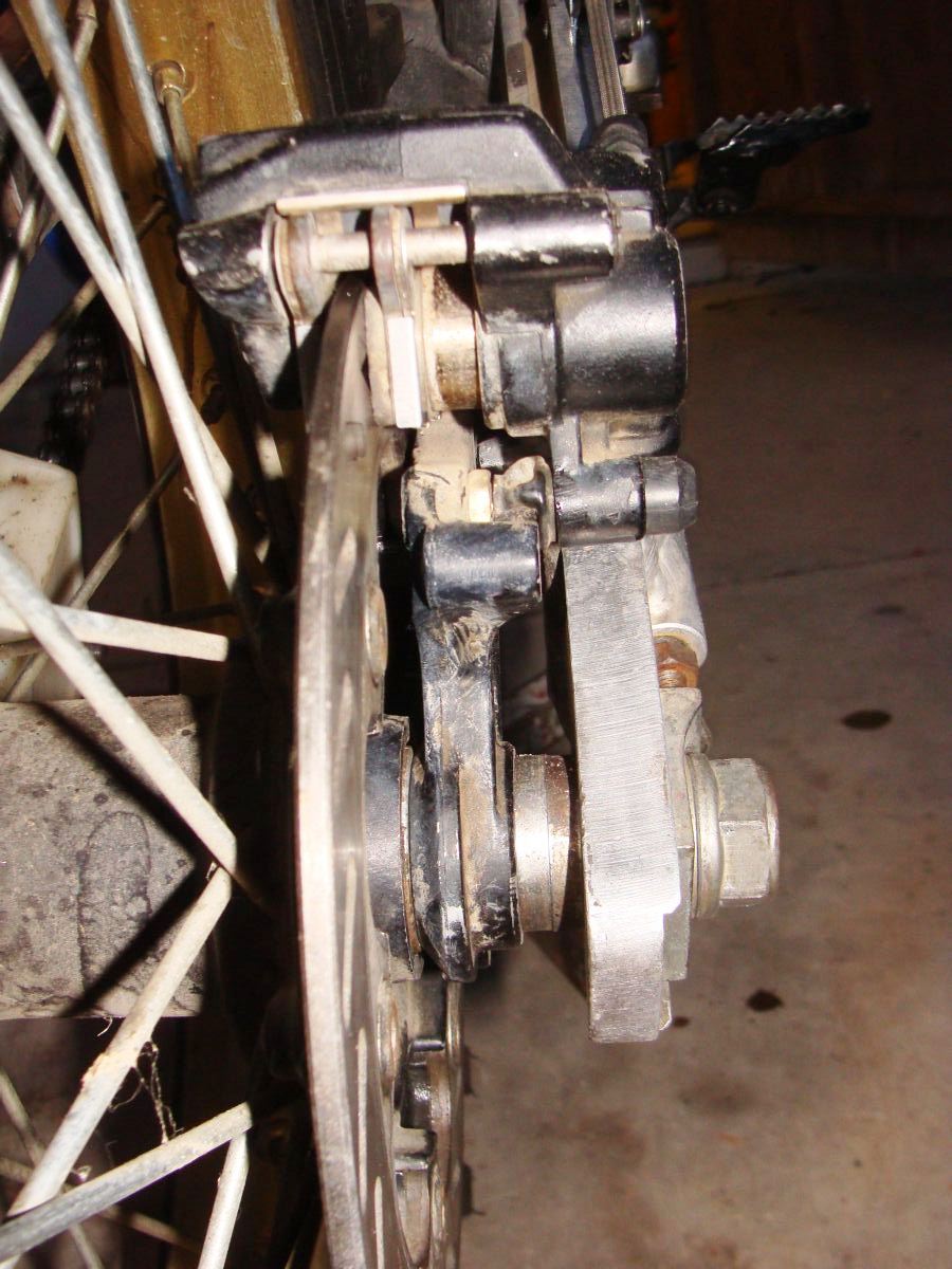
Looking at it, it looks like the rear piston is almost 7/16” extended from the caliper – isn’t that a bit much for having brand new pads installed?
I’m thinking it should be more like 3 – 7 millimeters or so?
Is it possible I have the spacers wrong?
1 step forward…
I’ll provide pix later, ran out of time tonight, just wanted to bounce this off my techie gearhead friends..
Don
Rear brakes and Air box
My 1$ rear brake reservoir arrived from MotoRecycler (great company) so I got busy and installed it, bled the rear brakes and what not. I'm not happy with the hose routing, it kinda rubs on the shock spring. Worse yet, the rear brake has very little braking power - can barely pull a skid even in dirt. On the good side, my brake light switch is fine!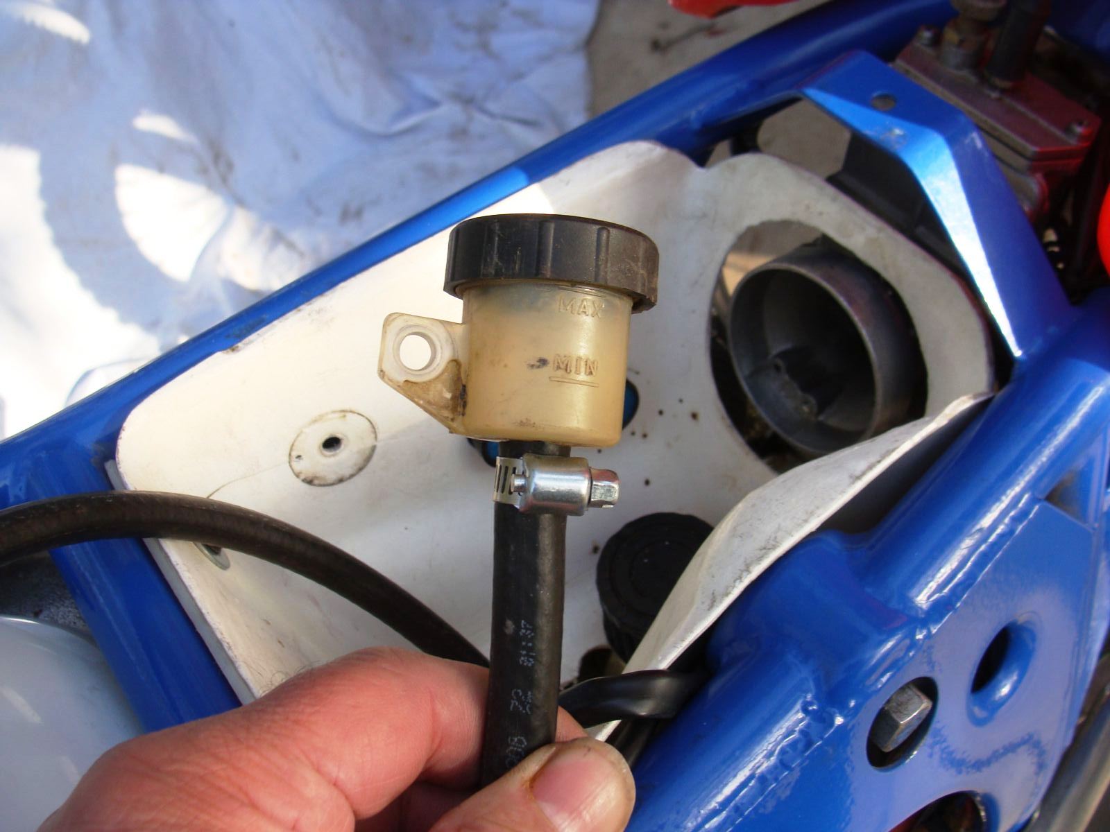
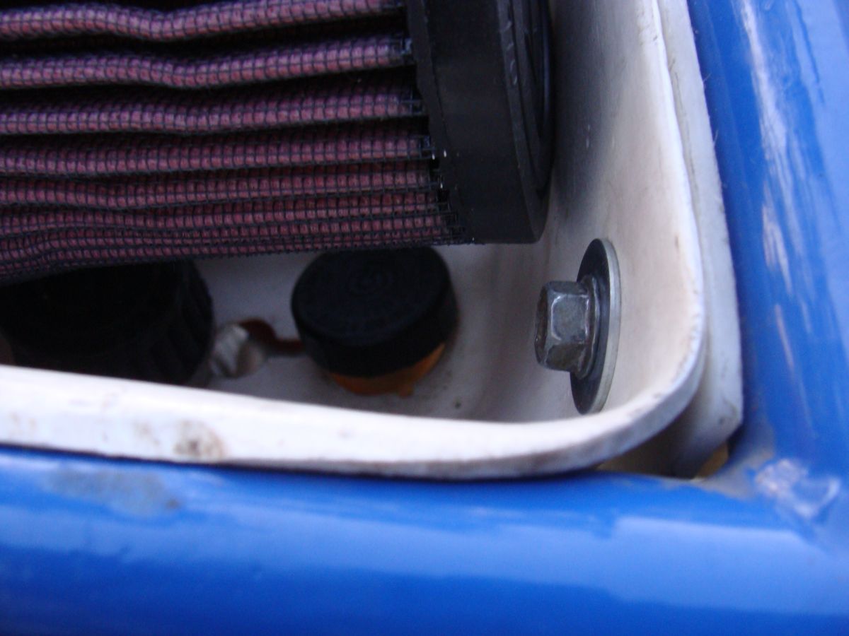
First things first - here's the wiring in the airbox and cut-down snowmobile filter. I'm not happy with the cut, used an Exacto, should have used a bandsaw, as the cut is a bit jagged, just does not look 'pro', *yet*.
Can you see the rear brake reservoir?

It's in the airbox, all nice and clean, protected from the elements!
..and here's the rear brake piston - it sure seems like it's sticking out way too far giving new pads are installed. Makes me wonder if I have the spacers installed incorrectly..
Nothing done at all
..last weekend. Rainy. Cold.
..and I went and stuck the tractor in an endless mud hole... sigh.
dumb ass...
2011-03-27 Clamps cut
Not much going on or time to work on stuff like the rear brake problem..
but I did get the clamps on the headlight assembly cut down to correct size...
celebrate the small accomplishments, they lead to bigger things!
...oh, yeah, got to cut that slider circle off one of these days too... <grin>
2011-03-29 ATK Porn
No other way to say it, MC porn, dirt style..

2011-07-03 Carburation
Leaking gas.
Pulled carb, cleaned, checked floats, all appears to be ok.
Reassembled.
The jet that the slide needle goes into is a 389. This part is the long and skinny. Pix to follow. Me thinks it's the needle jet female 1/2?
Drat. Still leaks.
Found old carb, exact same....
but it's hot in the shop, 108F..
..aargh and double ARRGH!
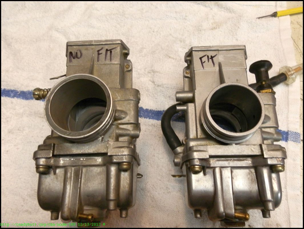
Went through all the work to transfer carbs and the freaking' things are different sizes! The old one off the ATK is smaller throat diameter than the one that came off the XR600. So I'm screwed and tattooed - it won't fit, period.
Maybe the needle and seat are transferable..
2012-12-16
Decided to show Ms. ATK some love. Several things I wasn't happy with -
On the stand, ready for fixin'..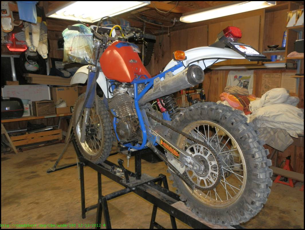
I spent 3 hours fabbing a mount from the right peg to the engine stand. and it bent on the first application of force. Oh well..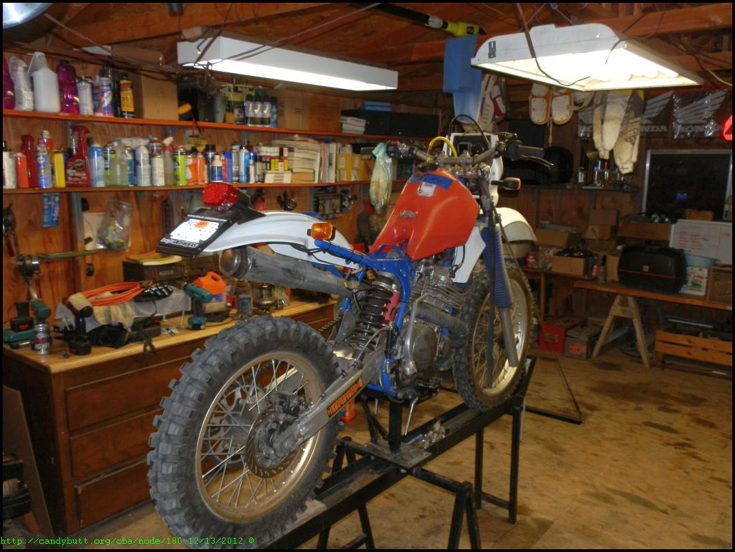
I like the FJR headlight reflection in the background. Hey! Let ME in the nice warm shop!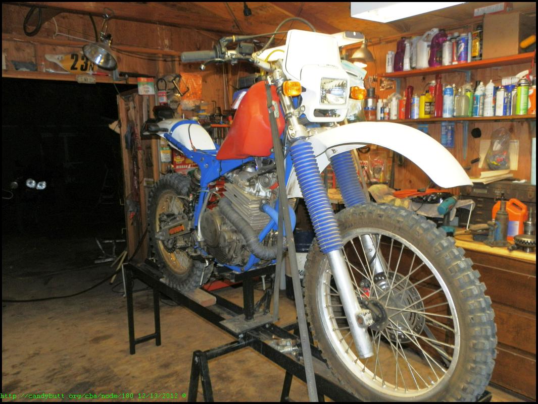
Here is where the O-rings were leaking. New o-rings, and straightening the holder bracket fixed it. Of course, I first had to remove all motor mounts but one, then jack the engine up so those stupid bolts could be removed. What a PITA.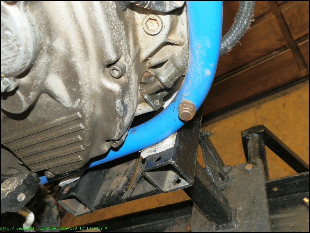
High tech at work...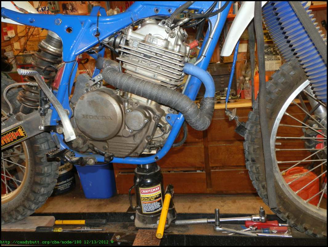
On to the carbs and leaky float valve. I have both these carbs. The No Fit carb had better main jet baffling, and the needle valve and seat looked identical. So I swapped parts. Made one good one out of both of them. And, apparently, it worked!
More pix later of modifying the rear fender for a better fit..
ATK ride
Derelict, how ever you spell it
Well DC I give you a challenge, Donnie and I along with others will be at PCV Jan. 3 to 8 (donnie birthday bash weekend) lets get the ATK's cherry on a its 1st/virgin dual sport ride.
Come one come all to see this monumental account of true coming out of retirement moment (rider and bike). Understanding I have chased this bike around a many MX tracks. Now its time to chase it to the 1st bar by way of dirt.
Thoughts, ideas, and option welcome
Gupster
2012-12-23 Suspension Off
Project ATK is getting closer and closer to being an bike actually worthy of abusing in the dirt as all good dirt bikes should be. Today got her 'lifted' off the suspension to remove forks and rear shock. I gotta say Thanks to my bud Gupster for building the bike rack and lift.. I'm getting to old to be crawling on the floor like the 'good old days'..
Front forks and rear shock ready for Independent Race Shop, San Luis Obispo, CA.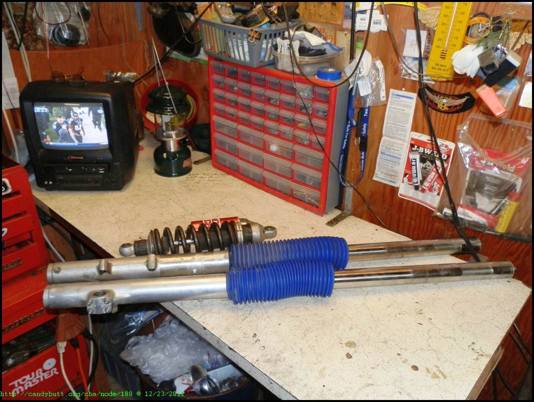
1989? CR 250 cartridge forks. Supposedly the 'ones' to have. After IRS gets done with them, I'll have a better idea of what they 'really' are..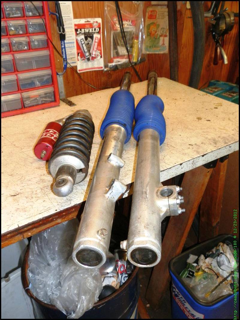
Yeah, it's a bit scary to put a 5k dirt bike up in the air with a 17k HD sitting underneath. That's why I have the big turnbuckles and custom jack under the ATK.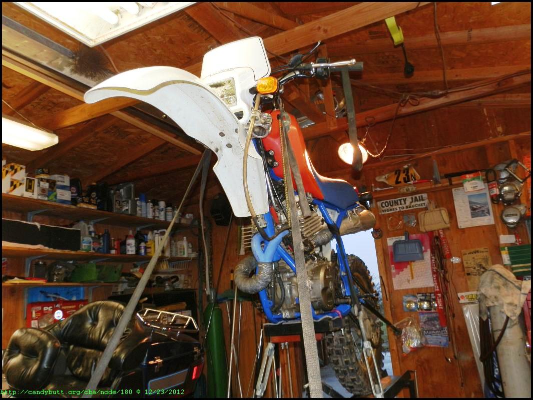
And TieDowns too!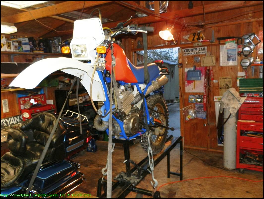
The exhaust is another issue I don't know what to do with.. The rear tire hits, it needs be spaced about 3/8" away. I'm considering just building a new system from scratch and be done with this headache.
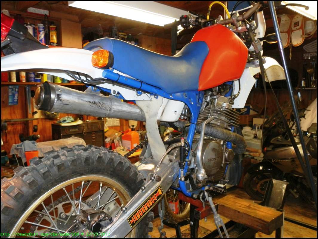
Naked, the forks are rear shock are both leaky. I hope severe corrosion hasn't eaten at the internals.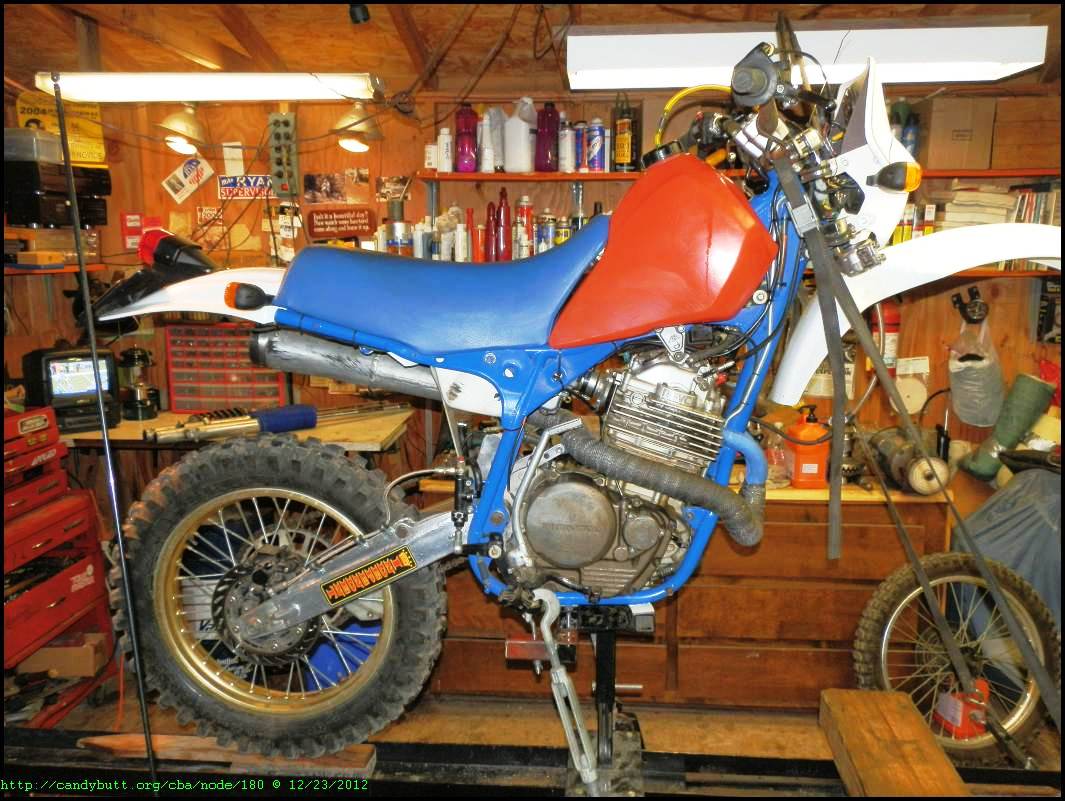
Back in the day, I had RaceTech do the work. Hopefully, IRS can do a good job locally for less money..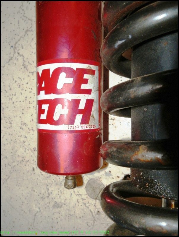
When done, this bike must be able to handle severe abuse, run reliably, and handle great. I have another motor for her, it was the race engine, which I'll detune, rebuild, and stab into later. Just because she is old school does NOT mean it can't work.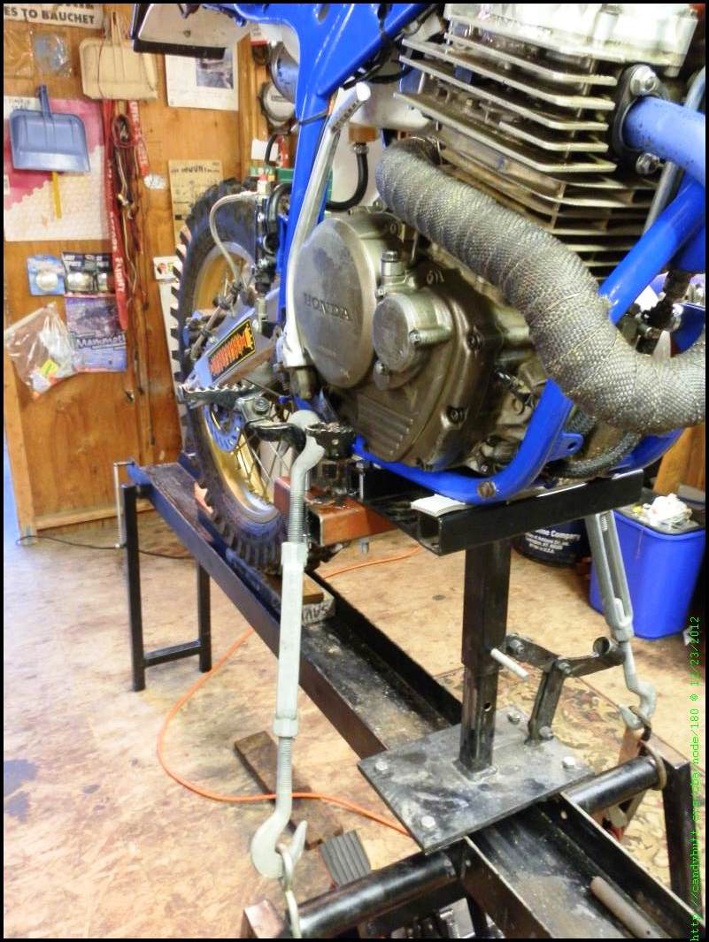
suspenders
DC,
Good progress, let me know how you like your suspender guy. I need to think about the xs sumo mod, lowering about 3' front and rear then revalving. You might quiz him about honda 88 xr rear and 93 cr front.
By the way, on the rack their should be 4 u-bolts to go around the frame to the rack not needing any straps, at least that's what I used to do on the old cr 500 when removing both ends. It looks good after all these years by the way.
Merry Christmas to all wasting time watching DC work his magic.
See ya next year,
GA
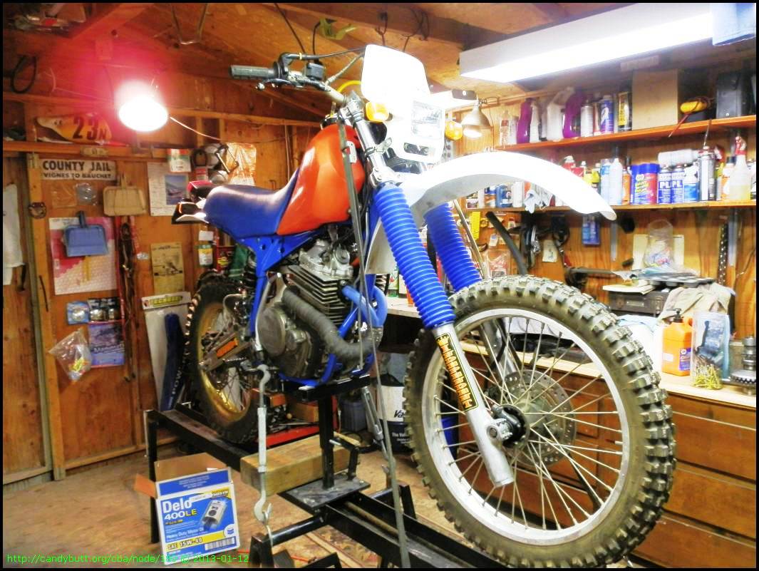
2013-01-12 Suspension On
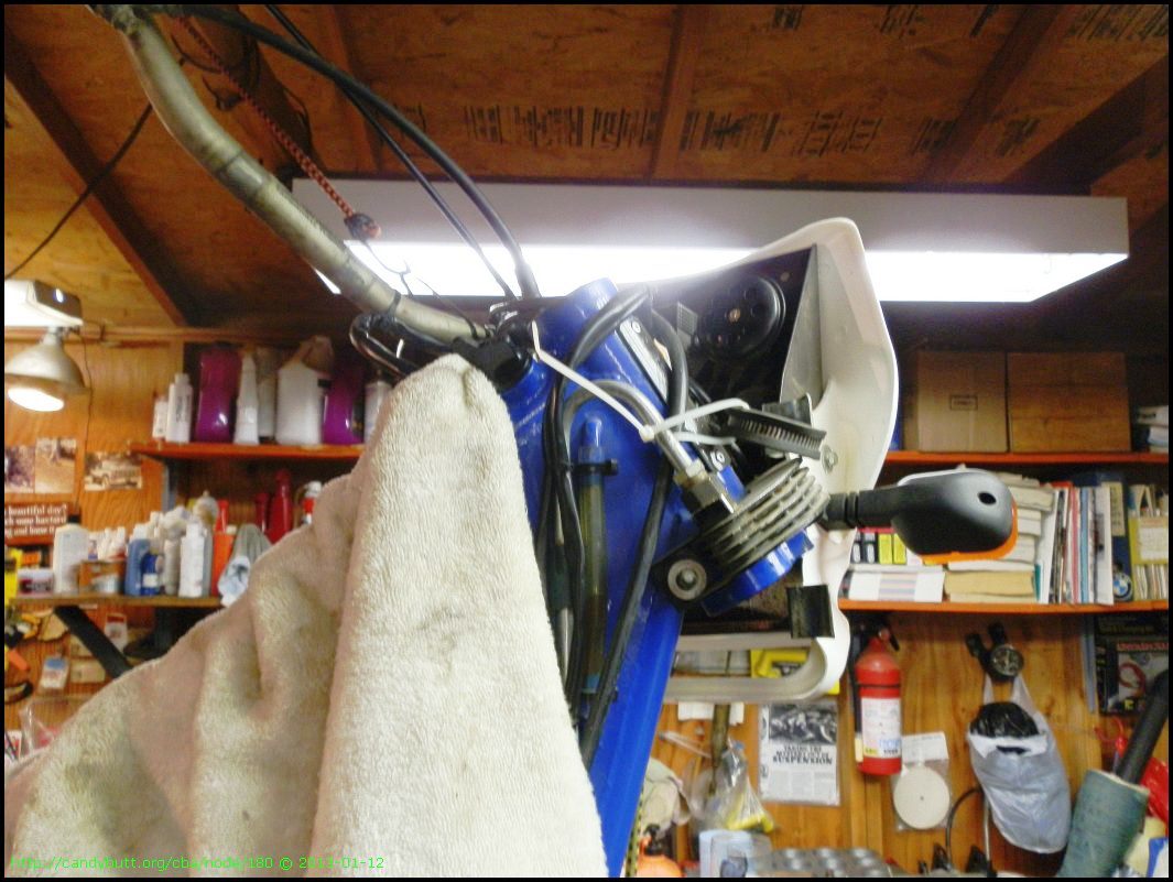
Got the forks and rear shock back from Independent Suspension. They are great guys, local, knowledgeable and fun to deal with.
First step, check steering head bearings for grease. There was plenty there, it was a waste of time. Kind of. The old grease didn't look like it was waterproof. The new stuff is.
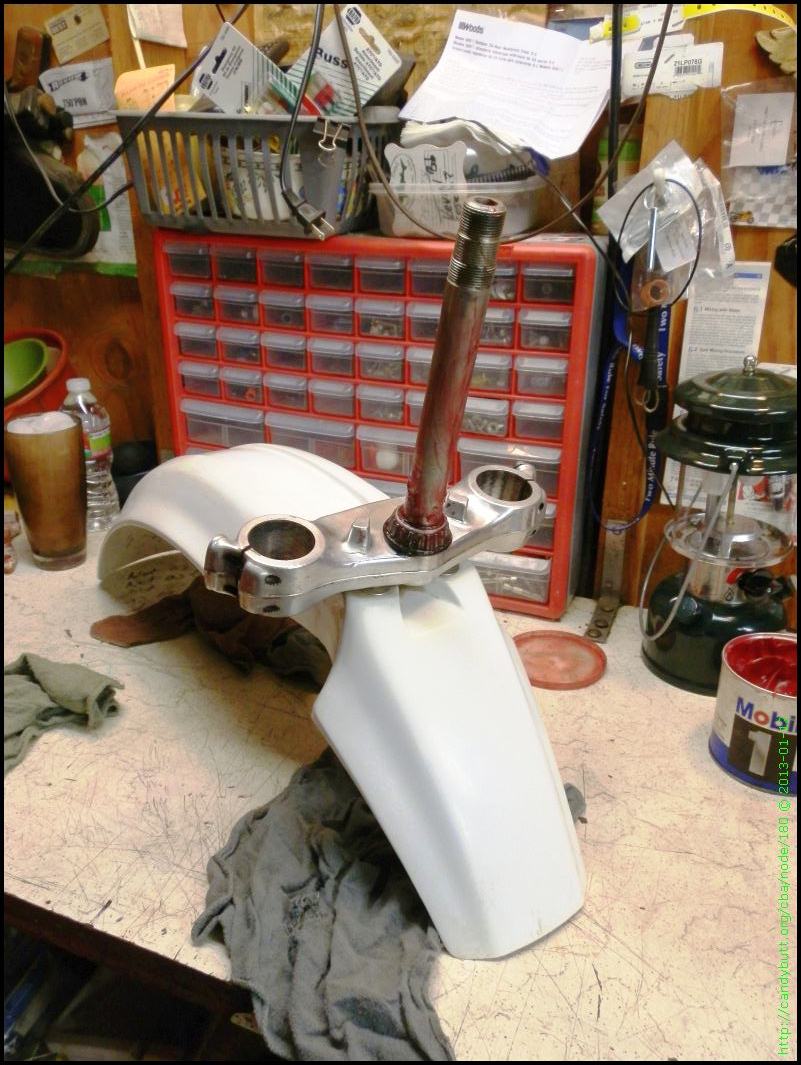
Handlebars hanging from the rafters! Someday, a lift with up and down adjustment is in my future.
Hell, I even cleaned the fork gotors!
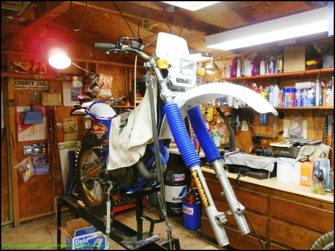
She's a purty thing!
Now that I'm getting closer to having a runner, I'm thinking more and more about rebuilding the 'race' engine.
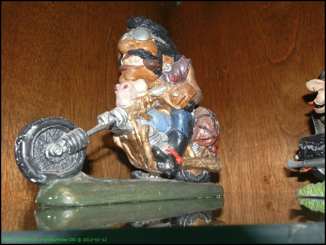
My buddy Paul, his wife made this for me back in the 1980's. Said it looked just like me! I still have it and love it...
2013-05-05 Engine Prep
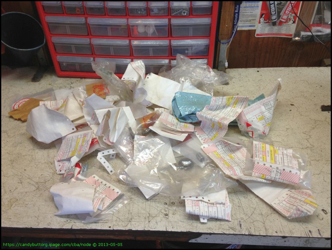
Time to rebuild the 'Race Engine' - this time with softer cam to ensure reliability. Max HP is not the key these days - I need a dual sport that can take long term abuse and still keep running.
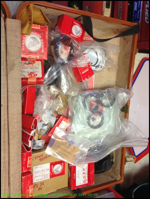
When I raced this bike, I always took lots of spare parts... and never got rid of them!
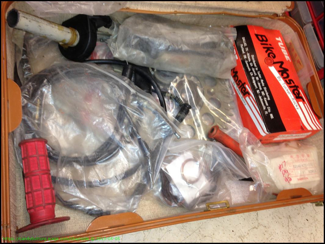
See what I mean?
Oil rotors.
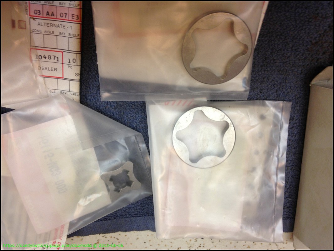 Oil rotoer
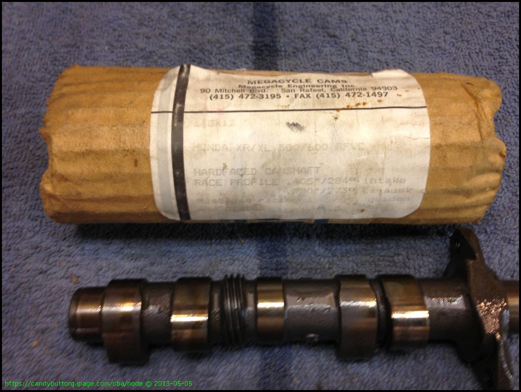
Spare camshaft.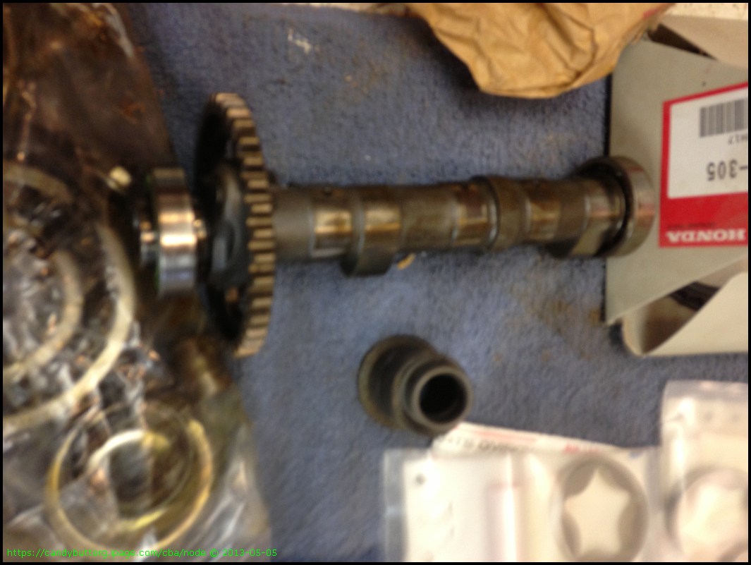
Spare ignition pickup.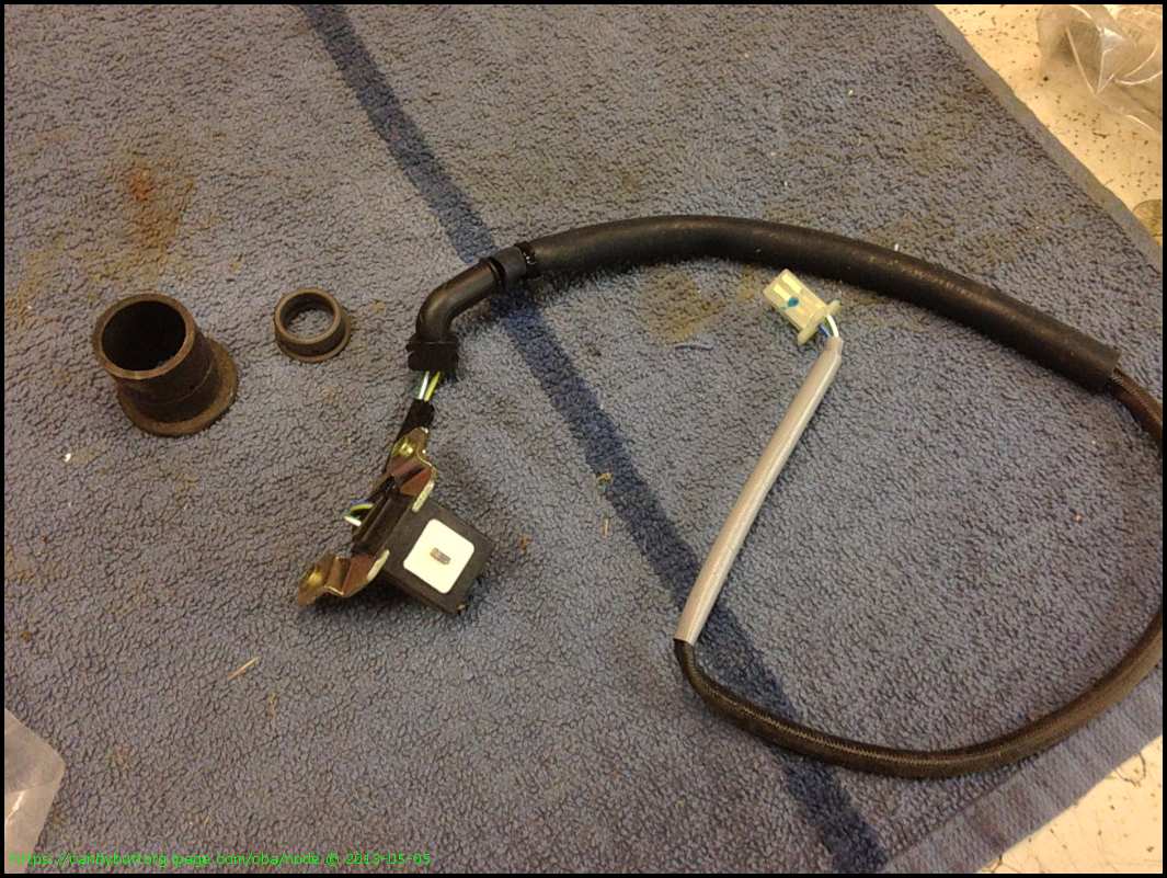
Bolts layed out in the patter they came out in.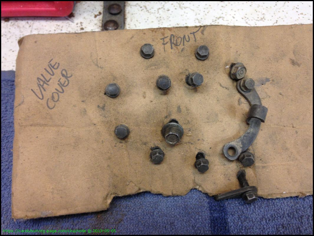
Oil Pump.
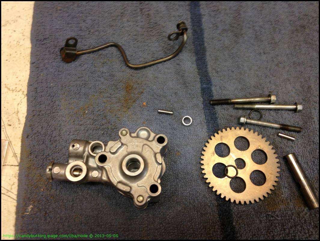
Wrist pin.

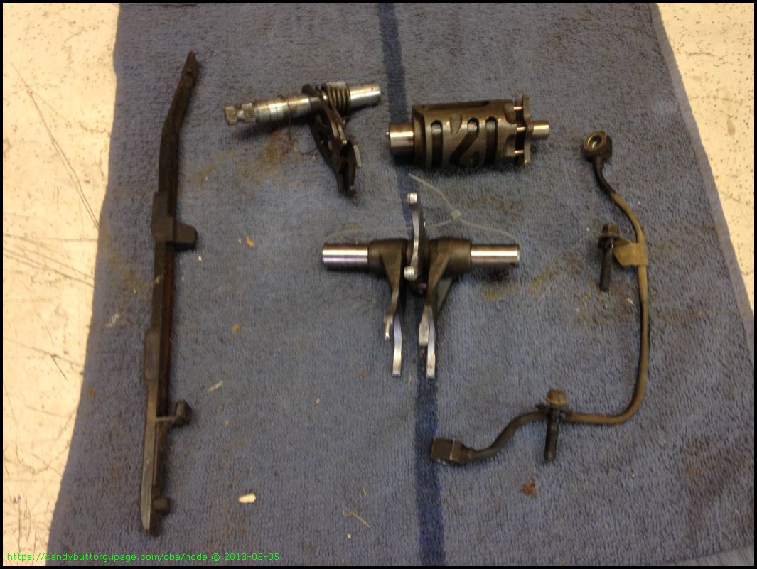
Shift forks, drum.
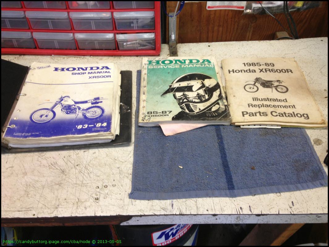
Manuals and parts books.
Transmission. With new gear sets.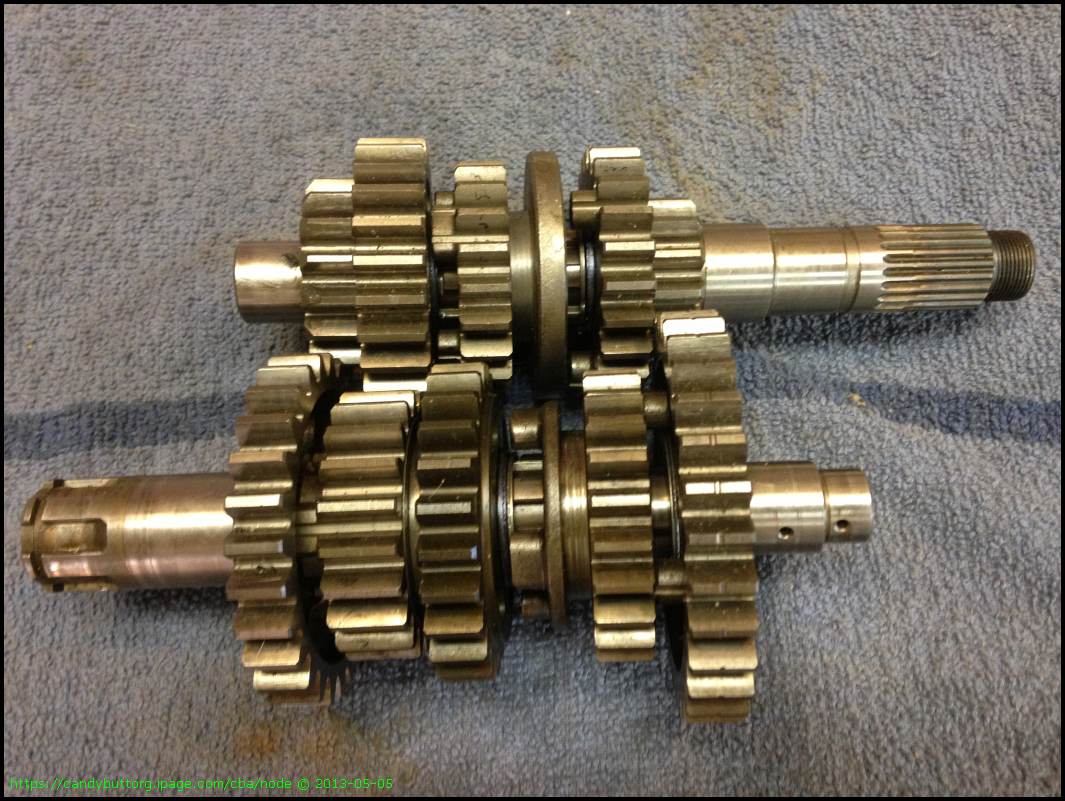
Unlikely buddies.
Cylinder and piston. Fresh bore.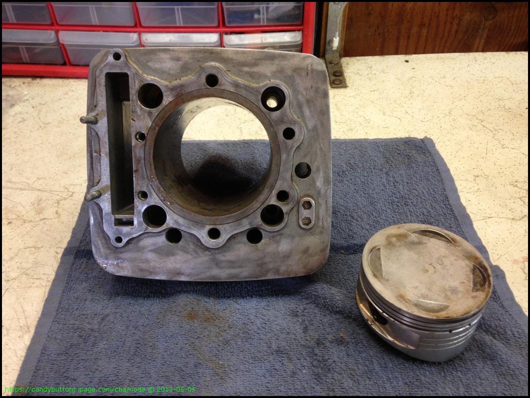
Spare valve cover. Ugly weld.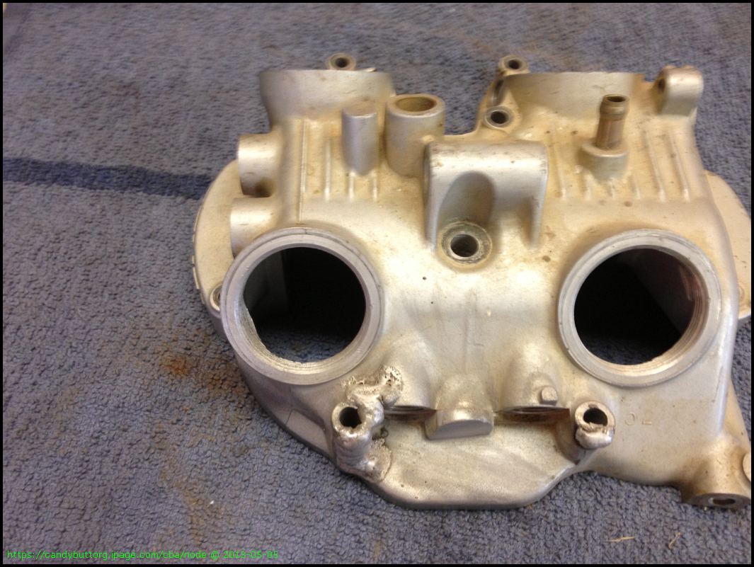
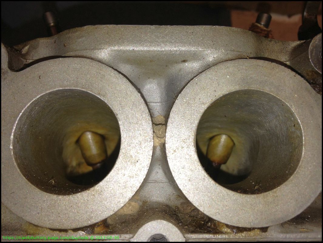
Flowed and ported head. New valves, guides, seals. Although the seals have been sitting for years now..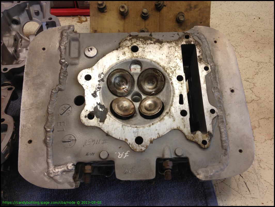
Purty.
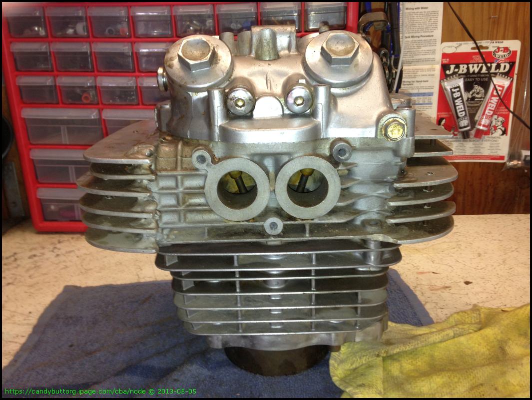
Ready to Run!
Center cases. Broken bolt by AFU marking.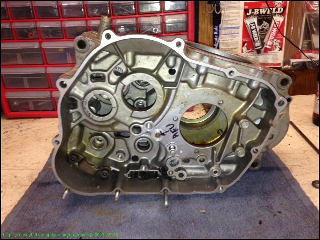
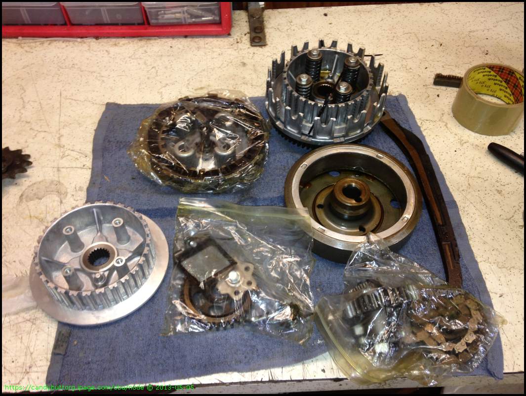
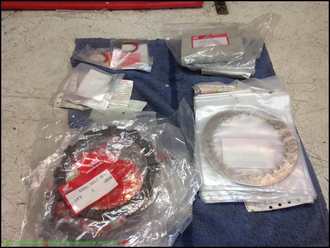
Clutch parts. I have new inner and outer basket that will go in . Rotor, oil pp, kick start assembly.
Counterbalancer.

NEW!
Crankshaft and Carillo H beam rod.
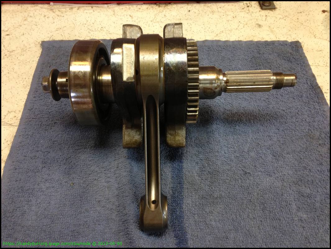
She's a thing of beauty..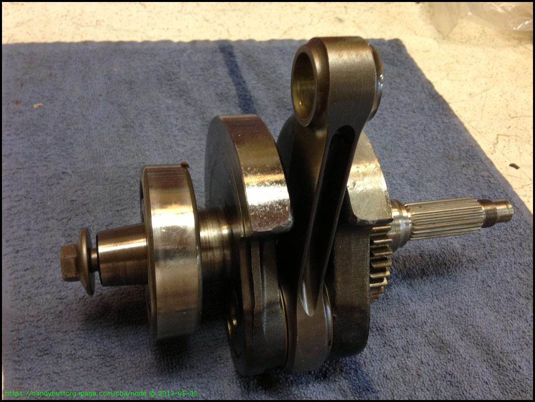
New OEM parts.. head bolts, seals, washers, exhaust studs...
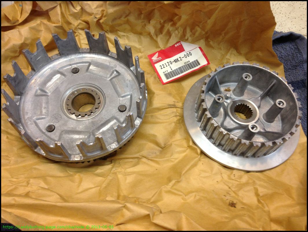
Yet another new clutch hub!
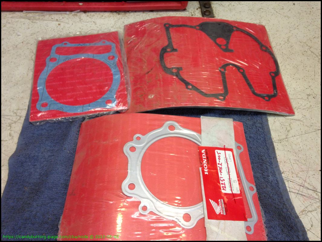
Gaskets..
Megacycle Cam.
New clutch pieces.
Well, that's it. Ray is getting a pretty clean package to reassemble.. not all rusted up, parts are tagged and bagged, with lots of new high dollar pieces. I'm really looking forward to getting this engine running as the one currently in the ATK is really, really tired. She blows smoke, has low compression, but she does run!
2013-07-27 ReRouteOilLine
Re-Routing the Oil Cooler Line - too close to exhaust header
What a PITA this job was.The line running up to the oil cooler was contacting the header.
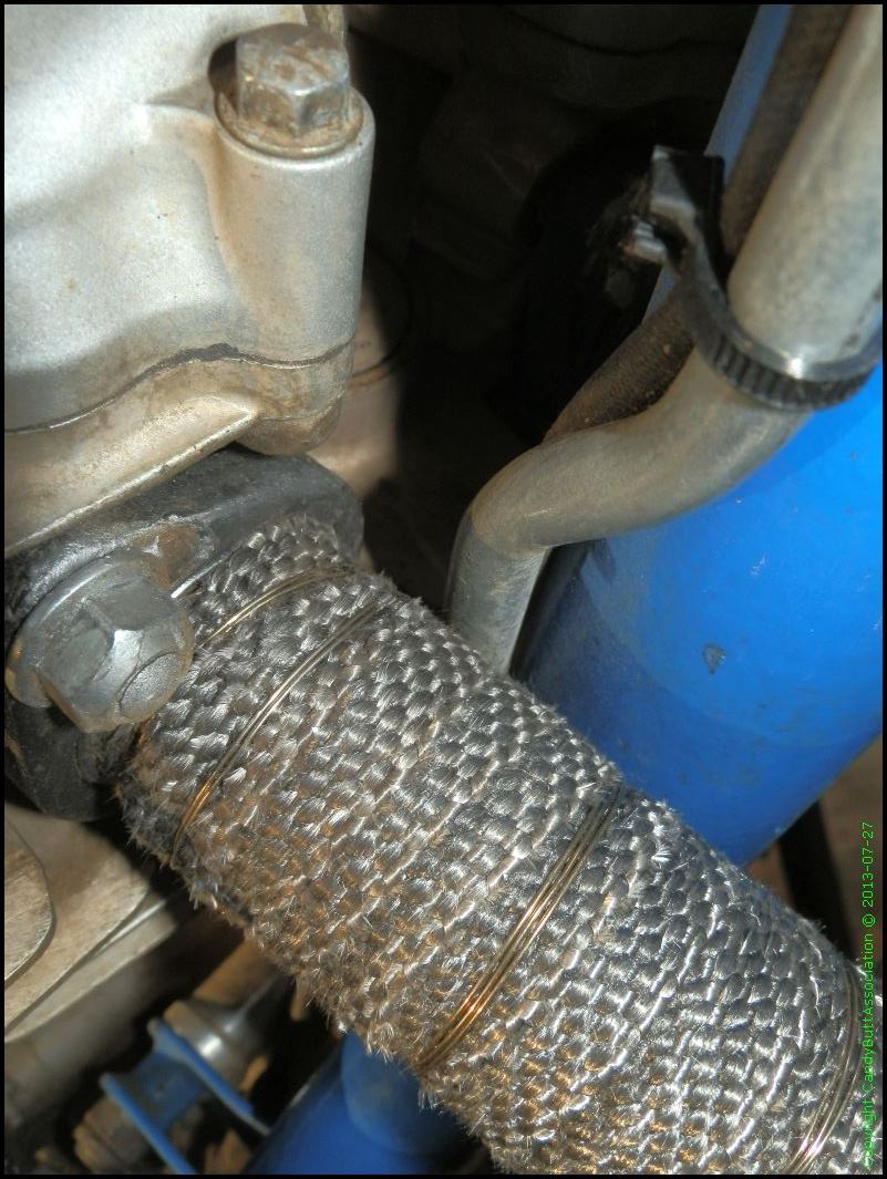
These pix don't show it, but I had to re-bend the line after pivoting the engine on the front mounts...
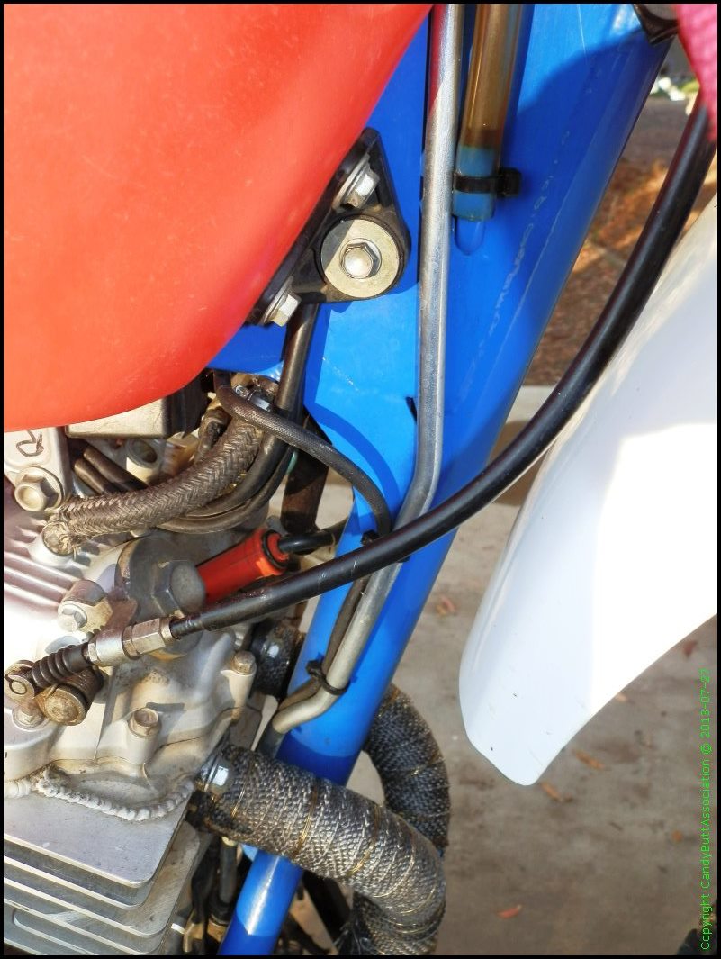
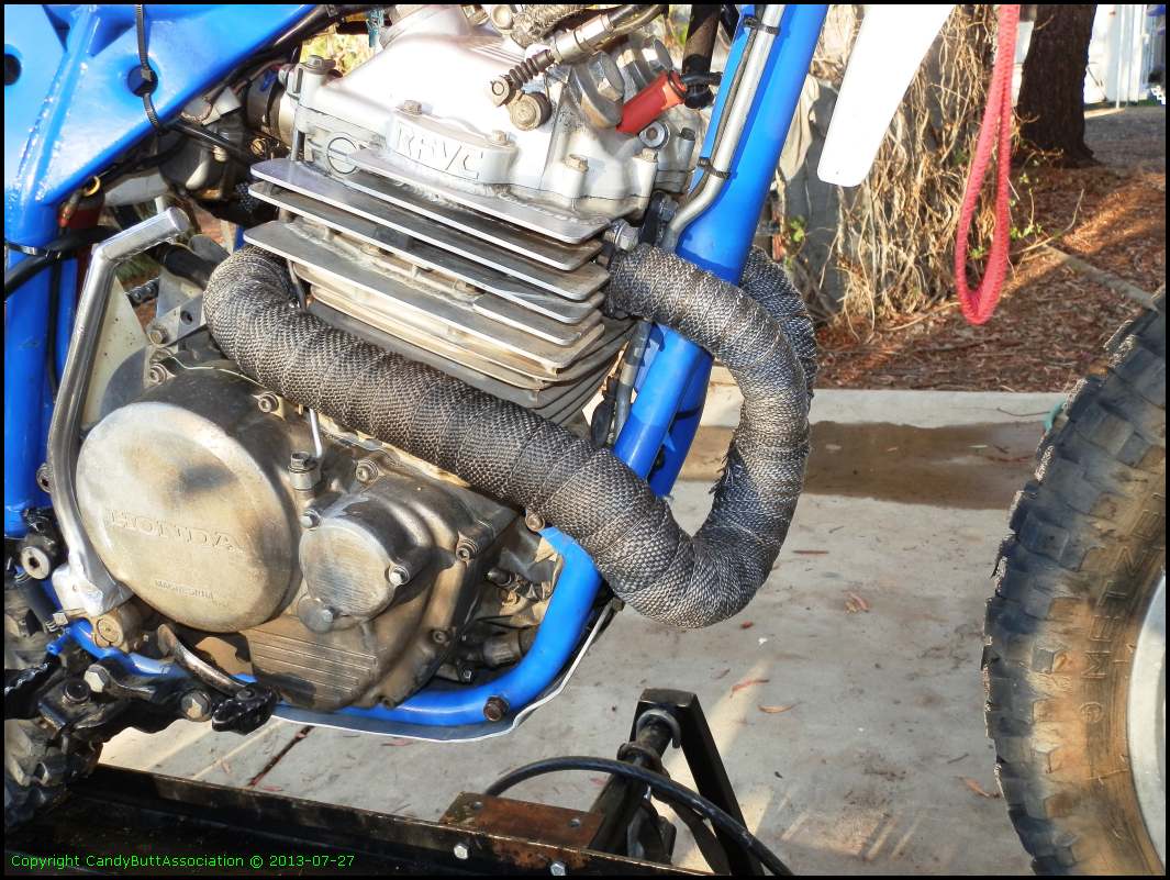
While at it, re-wrapped the header with heat tape.

Yes, the Ty-Rap has been replaced. This was a mock-up pix.
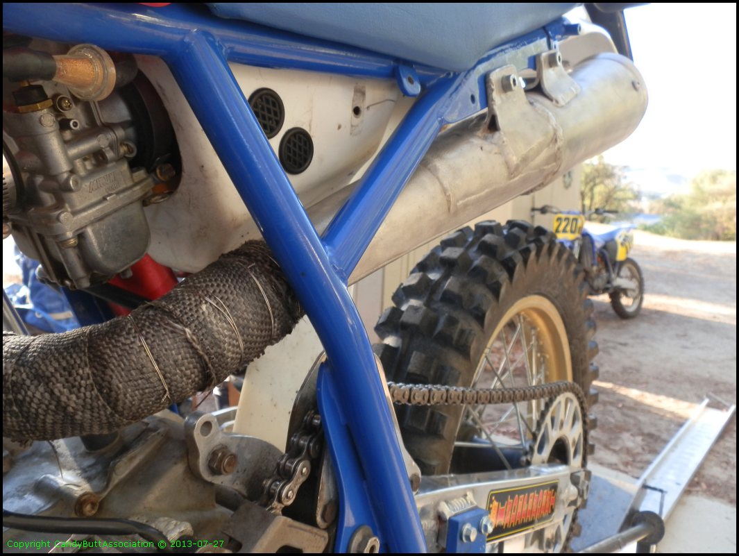
I need new rims and exhaust system.

I think the exhaust wrap turned out good.
I need a new silencer. Looking for an oval unit that will provide greater clearance to the rear tire.

x
If you have any ideas on how build/buy a custom oval silencer, let me know?

This is my 'mule' engine. The real motor is being built in La Pine, Oregon, by a fella named Ray.....
2013-12-28 Rims
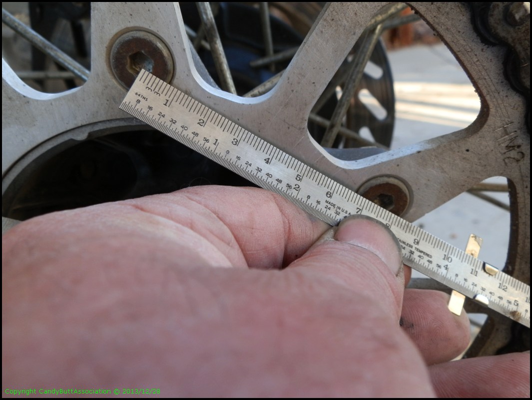
Parts / Components Identification Needed.
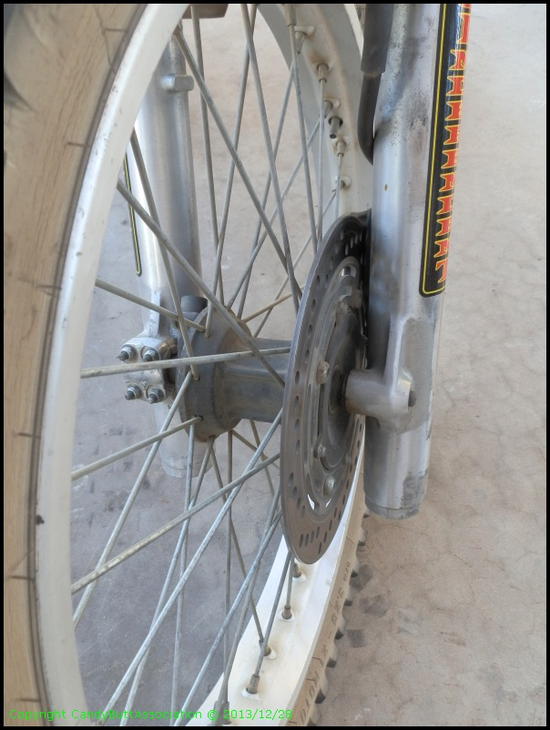
Both rims have cracks and need be replaced. You can see one crack in this pix at about the 11 position.
The trouble is, I don't recall what I have! Back in the day I bought CR250 front fork assembly from a local named Frank Villa.
I also purchased, at the same time, a rear end that had a Honda disk brake.
For some reason, I tend to think the rear end was off a CR500, while the front forks were off a cartridge CR250, supposedly the best available at the time.
My local small independent shop, HiddenPowerCycleClinic has complete hubs/spokes/rim assemblies available for cheaper than buying new rims and spokes. Sounds logical to that route. If only I really knew what I have!~
If you have old school Honda CR/XR knowledge please let me know as the new supplier has a no-return policy.
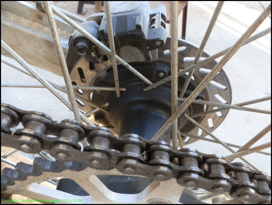
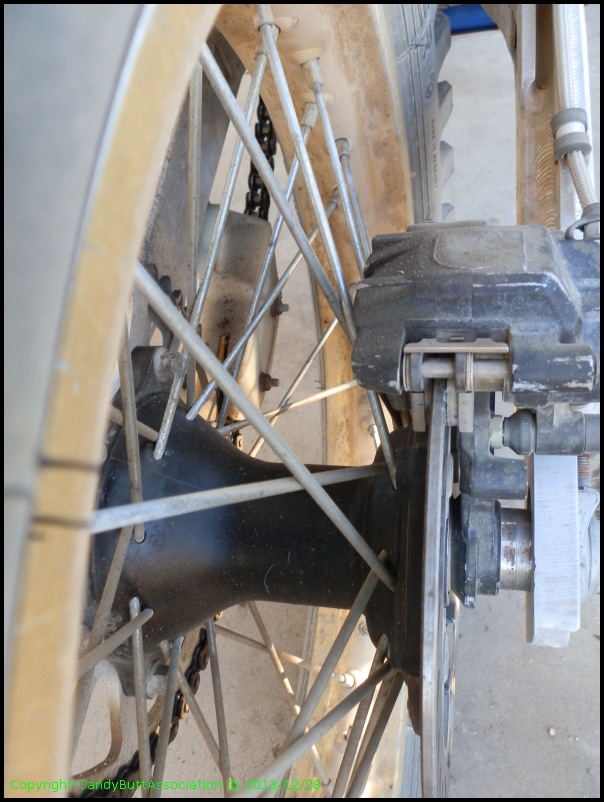
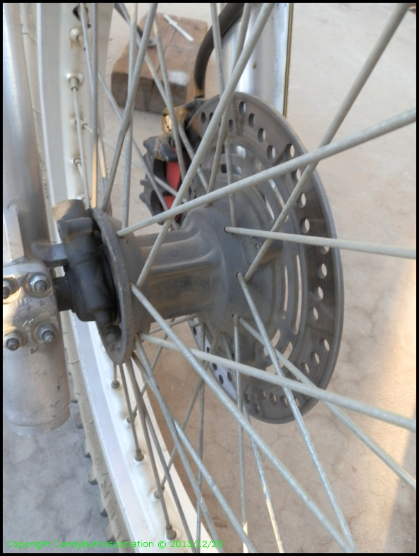
Here are some pix of the rear end.
75mm spacing between bolts, 6 mounting points.
Concial shape on the drive side.
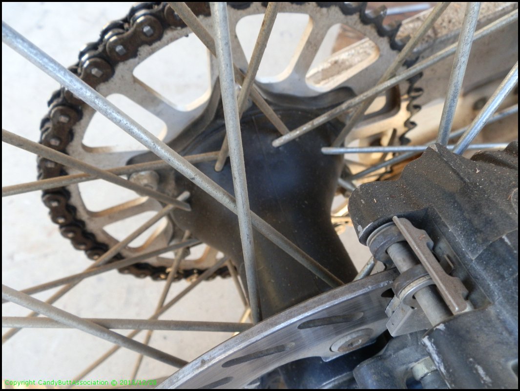
Views of the disk brake side.
The spacers on the right were to fit the assembly into the ATK rear swing arm.
Now, for part two of the mystery.. this is the front end, obviously. What Honda XR year might it best represent?
I bought the ATK new from Horst in 1987, so I'm thinking 1987.
It has the typical XR front hub speedometer driver mechanism, so the front end is NOT a CR, hub, spoke, rim wise.
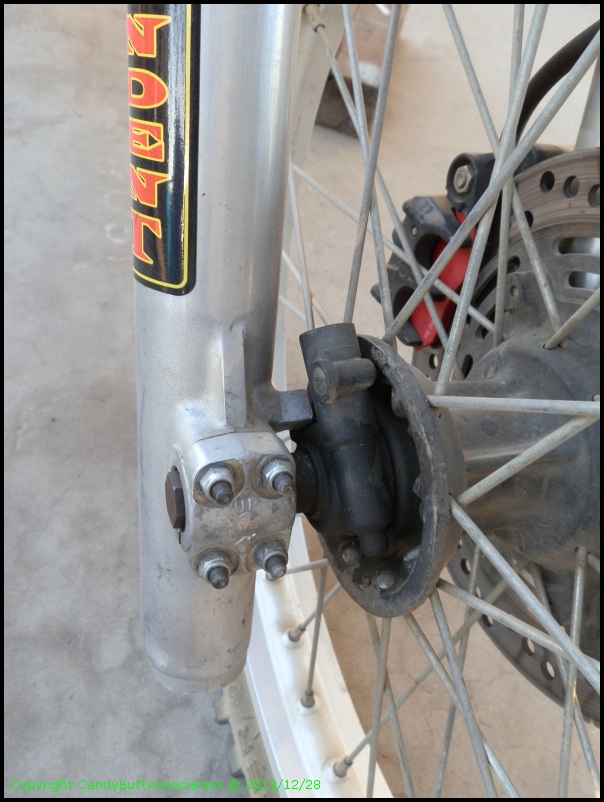
I do recall the axle having to be special machined to fit.
Man, this was a loooong time ago.
Brake side.
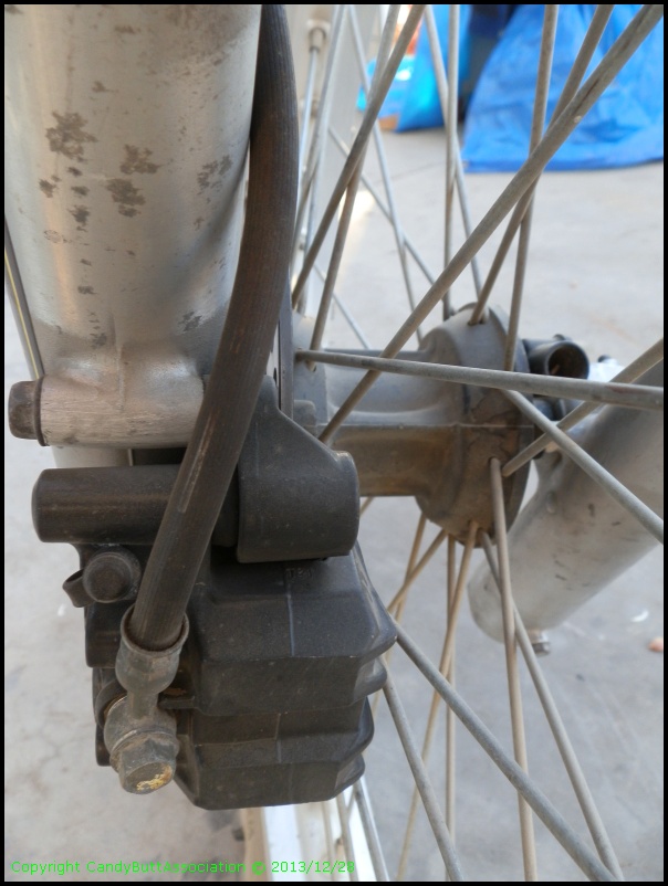
CR250 forks? XR rotor and caliper? Would you guess 1987 or?
Thanks for looking, and if you're an old dog with knowledge, please post up and let me know!
2021-03-25 Resto Finished.. moving on to Wrenching
2021-03-25 Resto Finished.. moving on to Wrenching