- Home
- Forums
- Ride Reports
- MotoBikes
- Restorations
- Wrenching
- 1963 BMW R69s
- 1969 BMW R60/2
- 1978 Yamaha 125
- 1979 KZ1300
- 1979 Kz1300 - Bob's Beauty
- 1981 CBX SuperSport
- 1981 Kz1300 Model A3 - Chocolatie
- 1984 Ford F250 XL
- 1987 ATK
- 1987 MowieMowie
- 1987 RotoTiller
- 1988 Honda Accord Lxi
- 1990 BMW RT100 - Barrie
- 1991 Harley Davidson FLHTCU
- 1992 Johnnie Deere
- 2000 YZ426
- 2002 Dodge Ram
- 2006 Carson RacerX Trailer
- 2006 Host Camper
- 2006 KrZy8
- 2007 Wabs
- 2012 KTM 690R
- 2013 Naomi - FJR 1300
- 2014-08-01 Air Compressor - Sears
- 2017 Kioti
- 2018 Toy Hauler
- 2020 Honda Fit
- 2021 Miscellaneous
- 2024 Log Splitter
- 2024 NeoDyne MC Lift
- 2050 test
- Lil Trlr
- Eats
- RIP
- PC Not
- Cages
- Test
- FJRF Best
- For Sale
Candy Butt Association
World's Wimpiest Riders
You are here
2022-01-16 KrZy8 Cruise Control Fail and Fix

Forums:
2022-01-16
I need Warranty Repair, Smitty!
Well, after 16 years of service the AudioVox CCS-100 cruise control installed by Smitty and organized by Fairlaner, has failed!
Go for the easy stuff first, right? So opened up the switch module to find this mess.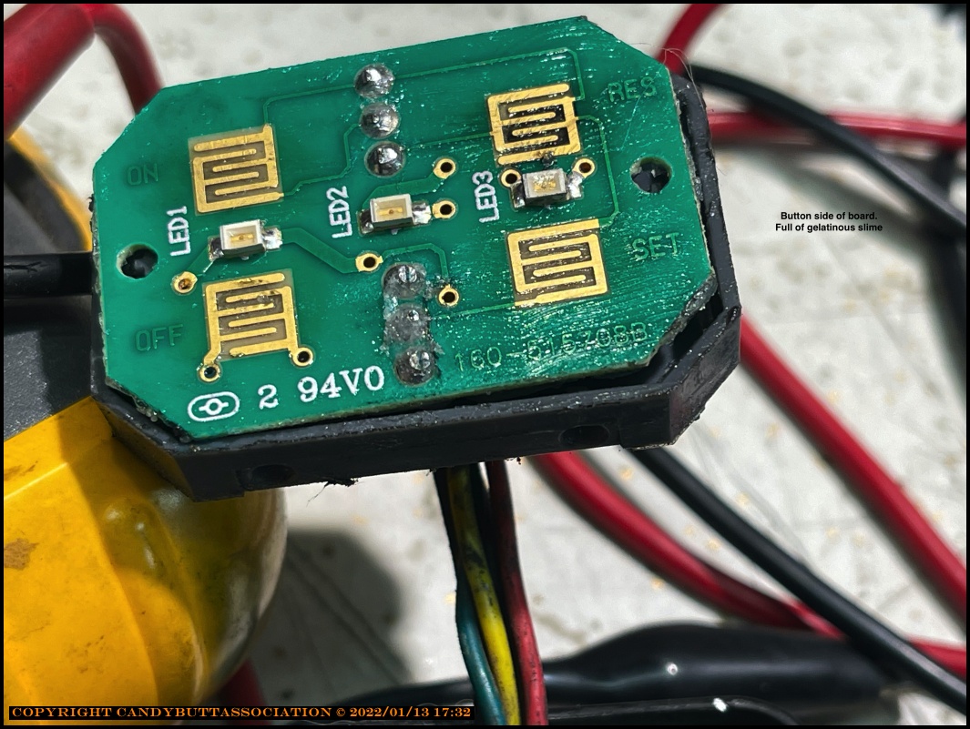
The control pad. Hmm. Not looking 'conductive' or maybe it's a conductive silicone of some kind?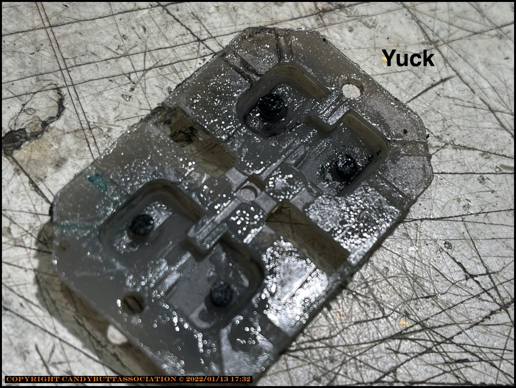
PCB board back-side.
Looks like it has, uhh, 'changed state' over the years?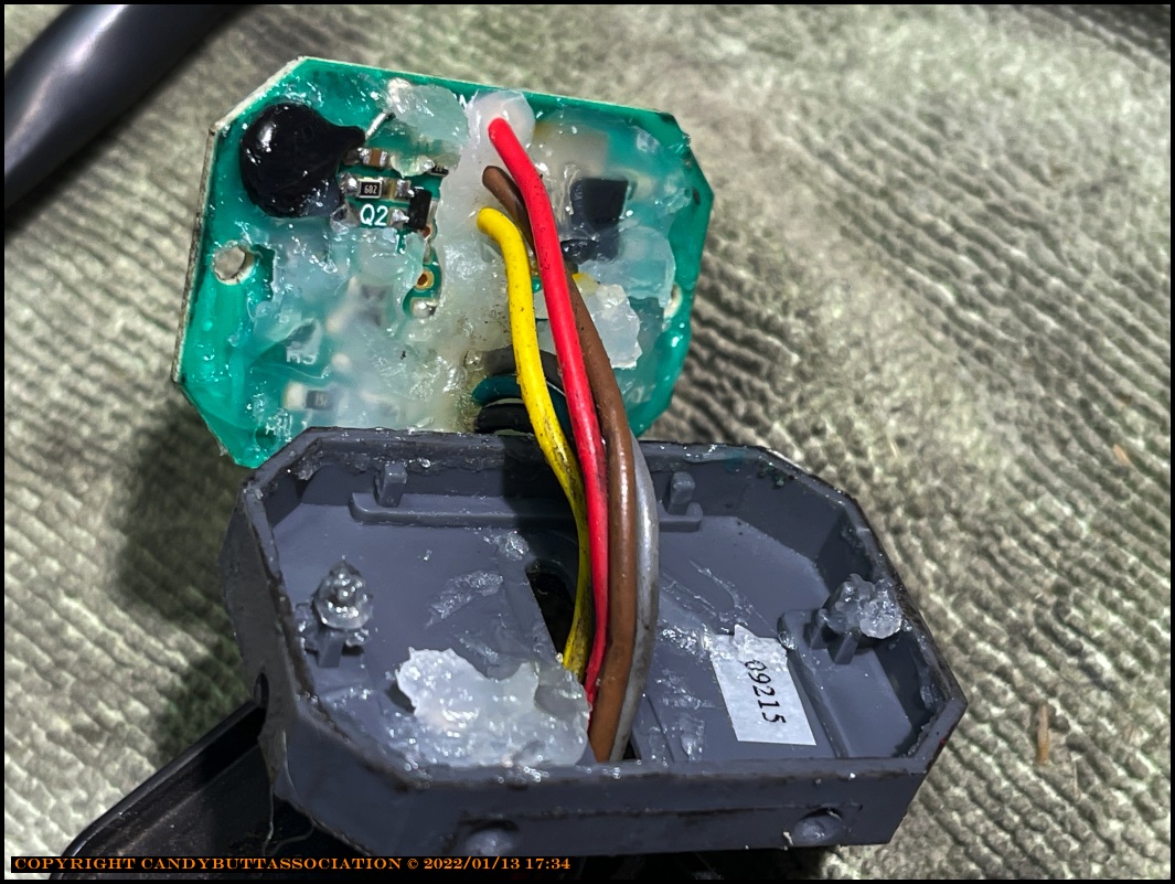
Noticed that Smitty took the time combine the red and gray wires.. Wonder why?
(Gray is for 'backlight' and Red is B+ for Set, Accel, etc.)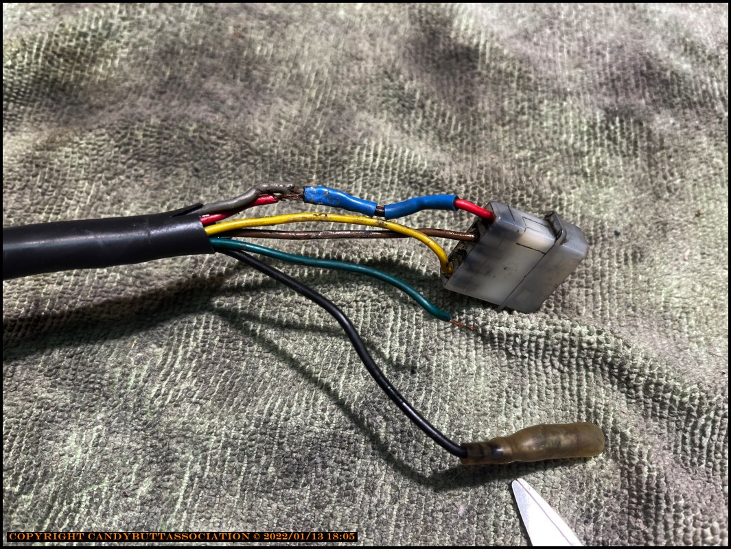
I was smart enough to A) buy a brand new one and a used one from 'back in the day'...
So have a used SkyWay machined housing and switch assembly, as seen by the pretty color coding on the
new-to-me switch cabling harness.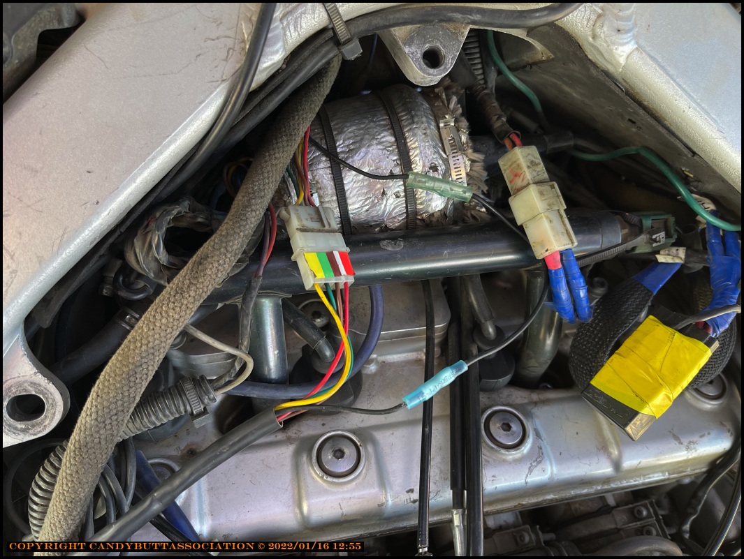
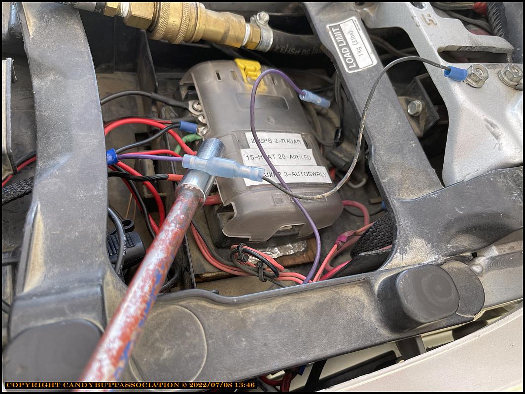
The 2006 module. Notice that positions 1, 4, 7 are 'on'. And the jumper at left under LED is removed for manual transmissions.
BTW, the LED is a diagnostic light! Power the bike and CCS up, press Set, Decel buttons and the light should illluminate.
MORE IMPORTANTLY, after energizing CCS, start bike and should see light blink indicating pulse signal from coil pickup.
PS
You can crank via starter, but let it spin for 10 seconds or so for light to indicate. As RPM's increase, light blinks faster.
At starting speed, kind of slow RPM and light response.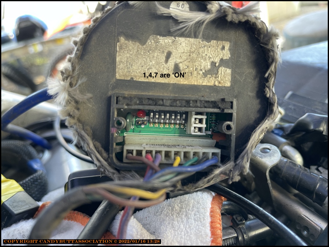
While jacking around with the connector, the green wire came out. Don't care, I have a used assembly to install.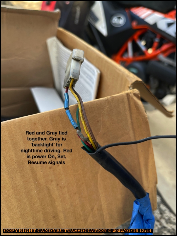
Coil pick off point for CCS-100. It's one of those stupid-ass blade connectors that penetrate insulation and mutilate the wire.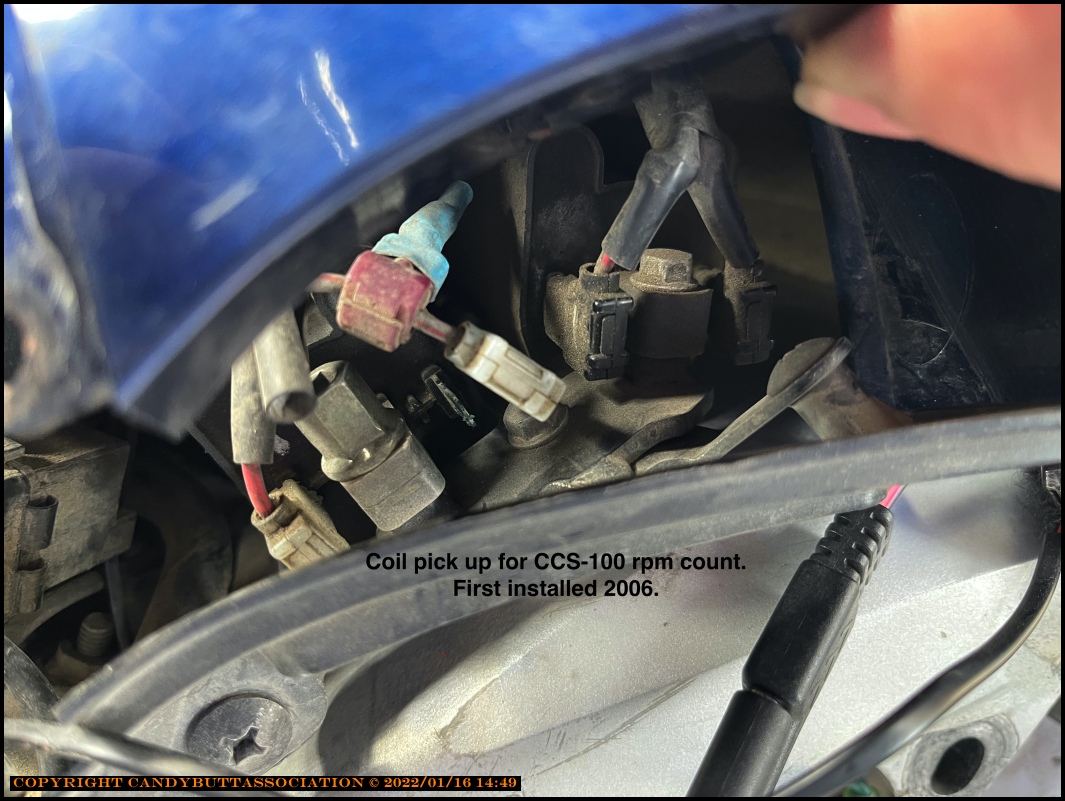
See what I mean? After years of vibration, the 'blade' stressed the wires into breaking. Look close..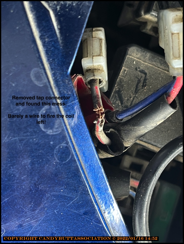
A pic of me to remember CCS-100 cable routing.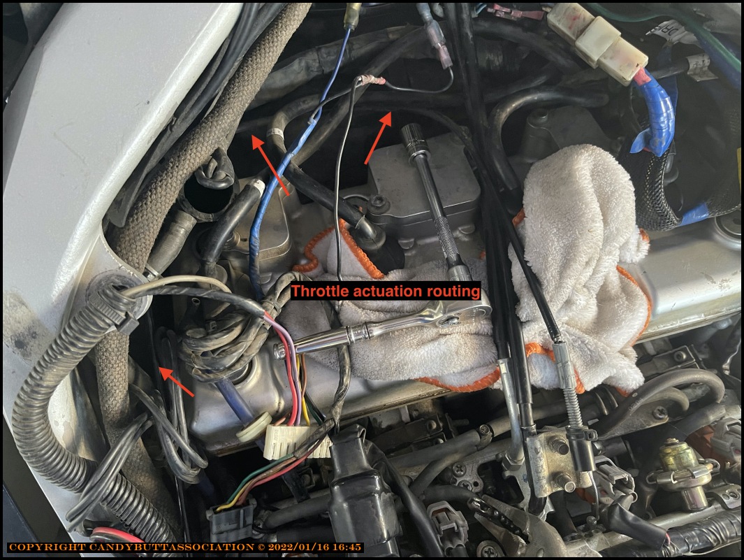
Gotta get pics of wiring fix... Was too excited to see LED light off when cranking..
Then again, with 2006 module, did not crank long enough maybe?
Theme by Danetsoft and Danang Probo Sayekti inspired by Maksimer
2022-02-14 NOT Fixed
Unfortunately, none of the above work fixed the issue.
Off to measure volts and ohmages...
2022-02-17 More Cruise Control Work
But, if it still doesn't work, I can access the Blue wire with ACV voltmeter. ACV should rise with RPM. I did crank the engine with tank off, and the LED did illuminate, but seemed like it stayed on and I didn't want spin the starter motor longer than needed.
Tomorrow will button everything up for a test hit on Saturday.
I wonder if the CC can be engaged and tested on the centerstand?
One last thought.. Measure the 'suppressor' resistance between 2007 installation one and my NOS in the box....
2022-02-17 Cruise Control Hard Notes
x xxxxxx
a
x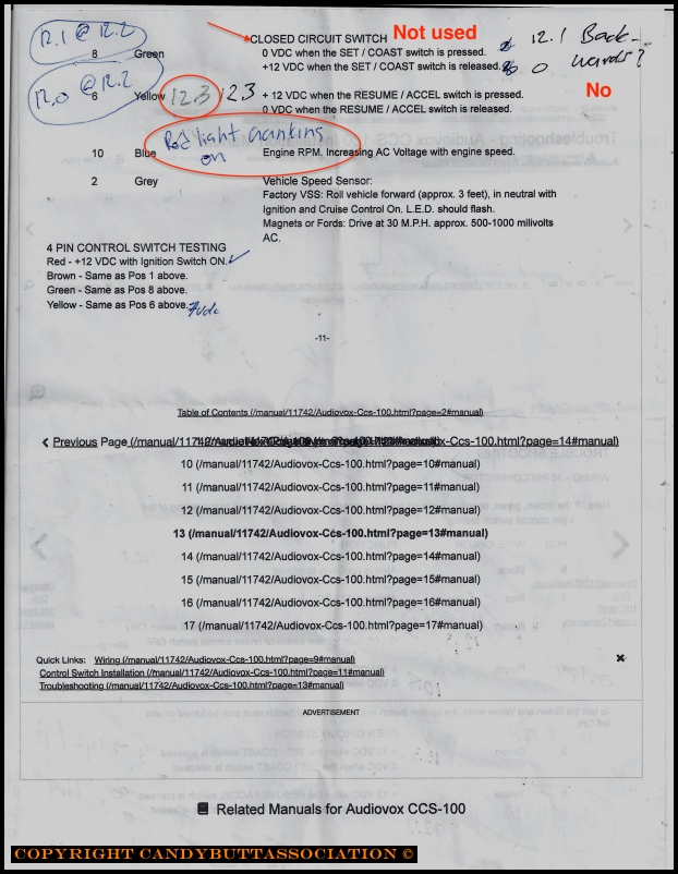
x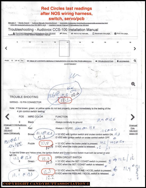
More testing
Thanks Ray!
All VDC at 4 and 10 pin are correct, with possible exception of 0.2 VDC on Purple <brake signal>. Going to disconnect Purple and test.
Tach signal from coil appears to be SAT
This video is VAC tach signal varying w engine RPM, frequency
This is VAC w/ engine RPM
Not sure what they should be but will measure 'suppressor' resistance between installed unit and NOS.
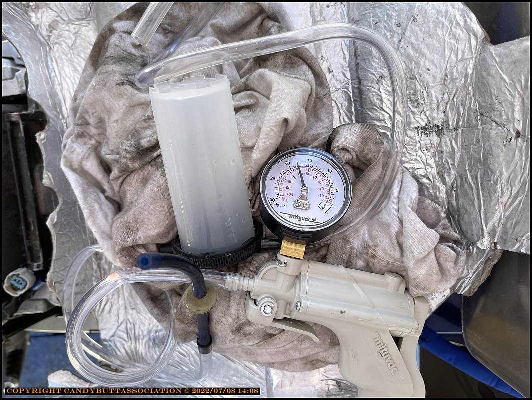
Bought a new MightyVac and will test vacuum 'circuit'.
I did check, both rear brake light, incandescents, are SAT. Will remove the LED brake activated license plate from circuit just to troubleshoot.
?? Should the 1 way vacuum valve be with arrow pointing away from vacuum source (inlet port spigot?)
2022-03-01 Vacuum Test and Disconnected?
Bought a MightyVac to test vacuum integrity.
Chose the right nipple, disconnected tubing at TB inlet, pumped the handle and...
NO VACUUM!
Checked the nipples again, made sure the clear MightyVac hose was tight. Still no vacuum!
And that's when I noticed the on-board vacuum line was disconnected from the servo module!
WTFO?
Did it disconnect when I removed heat shield?
Did I never connect when last working on it?
Don't know. But connected it, and she appears to be system tight.
Will test next week if possible, but I'm kinda running out of time before I go back to nuclear jail.
Oh, also added a connector so I can easlily disconnect brake lights from cruise control circuit should it still not work. e.g. can test while on the road.
Having to trailer out 5 miles really hampers the quick test ride.
2022-07-08 Back at Cruise Control problem
Still not fixed.Things checked today.
Results
Servo brake light lead wire grounded. Verified ground using voltmeter.
Check valve vacuum test SAT.
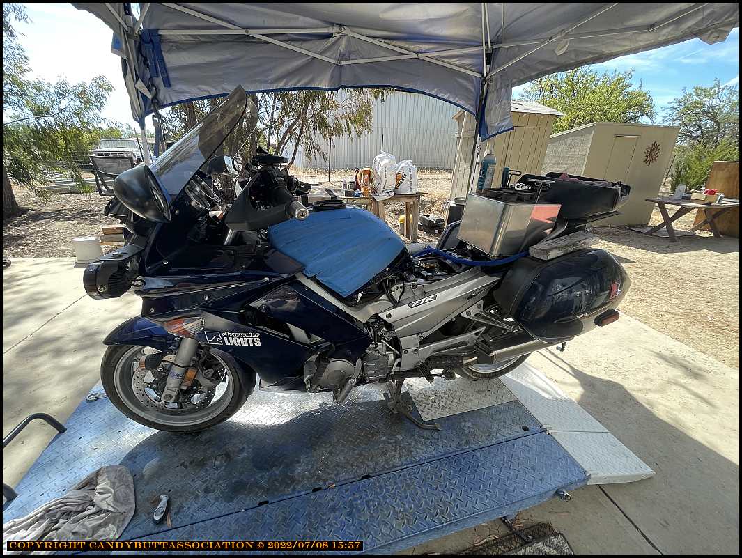
The situation.
2022-07-09 CC PulseMeasurePart2 from dcarver220b on Vimeo.
Engine vacuum from throttle body port #1
.
After all that, a test ride and FAIL. So dissapointing.