
Troubleshooting done so far -
- Disconnect BlueSeas (and by association, all farkles)
- Check 25A headlight fuse - hot on both legs
- Remove Brodie ignition harness - just in case?
- Headlight relay 'clicks' OK - for whatever that's worth
- Test Soltek lights - OK. Inference is that since Solteks connect to high beam wiring via AutoSwitch, any problem (short) would yield Solteks inoperative.
- The AutoSwitch has a bi-color LED that illuminates when transitioning from low beam to high beam (trigger) then again from high beam to low beam (set). It is NOT illuminating at all.
- Pulled headlight relay - NO power at either of the heavy gauge wires (blue-green? and yellow)engine running or not.
- Headlight relay does have power on one 'pin', engine on or off, ignition on, when high beam is selected. See diagram below.
Hi/Lo beam relay, connector viewed female side
-- --------- --> Grn/Blue
----------- --> Yellow
pwr ---> | | |
hi beam on
It appears that either:
- No 'B+' power is available to be switched by the relay
- The 'Engine is running' signal is not
Questions?
- Do headlights source power via ignition switch? Any possibility the iggie switch is bad?
- Where can I check the 'Engine is running' signal and how does it control the headlight circuit?
- What to check next?
Thanks in Advance guys -
My troubleshooting tonight was cut short by early darkness and the fact I'm bone tired from doing actual phsycial work this last weekend, 
BTW, the failure occurred, or was first noticed, at startup this AM. Hmm, thinks me, I have my aux Solteks wired in parallel (direct via relay and via OEM headlight circuit and AutoSwitch) so I'll just ride to work with Solteks. Of course, just my luck, I blazed an CHP on 58 in early dawn light, he lit me up, pulled me over, but he was nice and let me go when I explained the situation and proved my headlights were dead and it IS getting into deer season out here and running blind on a bike is dangerous and I need to keep my job and..... A LEO who understands = priceless and having a backup bike (Wabs) = Beyond Priceless! 
--------------
Posted 26 September 2011 - 08:43 PM
Wire colors:
Headlight relay:
Red/yellow 2 times, key-switched 12V
Yellow/white, grounded by ECU on engine startup to energize the relay
Green/blue, 12V to hi/lo relay when this relay energizes.
Hi/Lo relay:
Green/blue, 12Volts from headlamp relay
Black, ground
Blue/black, 12V from dimmer switch when high beam is selected
Green, 12V out to headlamp low beam
Yellow 12V out to headlamp high beam
There will be no 12-volt level at the hi/lo relay if the headlamp relay isn't working. Lights need 12 volts on the Green/blue. If the dimmer switch is set to high, you'll see 12 volts on the Blue/black wire and the relay will click, but no lights work. It just selected hi beam, but without 12V on the Green/blue there's nothing to switch from high to low. The hi/lo relay will click with the key on, without engine start, just by flipping the hi/lo switch on the grip.
You're troubleshooting the wrong relay, I think. The fact that you say the Green/blue wire is not hot with the engine running tells me the headlamp relay (the other one) isn't working.
 wfooshee, on 27 September 2011 - 06:27 AM, said:
IF is still in question. I've seen a lot of troubleshooting take place because the basics weren't checked first. Testing the headlight bulbs is simple and pretty much error free. Having 12 volts on the G/B wire is conditional whereas testing the bulb itself is not. That said, Don has proven to be pretty good at diagnostics without rookie errors so I'm pretty sure the bulbs are good but... let's just be sure before burning a lot of time and effort chasing ghosts.
As Walter says, with the engine running, at the headlight power relay, there should be 12V on the Red/Yellow all the time and the Yellow/White wire should be ground. If these conditions are met there should be 12 volts on the Green/Blue wire. If the running conditions are met and there is no 12V on the Green/Blue wire the relay is most likely bad, something that can be tested and confirmed.
--------------------
Posted 27 September 2011 - 07:58 AM
wfooshee, on 26 September 2011 - 08:43 PM, said:
Wire colors:
Headlight relay:
Red/yellow 2 times, key-switched 12V
Yellow/white, grounded by ECU on engine startup to energize the relay
Green/blue, 12V to hi/lo relay when this relay energizes.
Hi/Lo relay:
Green/blue, 12Volts from headlamp relay
Black, ground
Blue/black, 12V from dimmer switch when high beam is selected
Green, 12V out to headlamp low beam
Yellow 12V out to headlamp high beam
There will be no 12-volt level at the hi/lo relay if the headlamp relay isn't working. Lights need 12 volts on the Green/blue. If the dimmer switch is set to high, you'll see 12 volts on the Blue/black wire and the relay will click, but no lights work. It just selected hi beam, but without 12V on the Green/blue there's nothing to switch from high to low. The hi/lo relay will click with the key on, without engine start, just by flipping the hi/lo switch on the grip.
You're troubleshooting the wrong relay, I think. The fact that you say the Green/blue wire is not hot with the engine running tells me the headlamp relay (the other one) isn't working.
Aha! Was not aware that 2 relays are involved.. I wonder the where the 1st relay, or 'source' relay is located? My Hi/Lo in under front left panel.
bramfrank, on 27 September 2011 - 03:46 AM, said:
If indeed you have suffered such a failure you must file a report clearly stating what has happened with the NHTSA. Yamaha cheaped out on the recall and only replaced the main harness when there is the front sub-harness that can also fail and take out your lighting - more likely in fact after the recall has been performed than before.
I can see another recall coming.
Keep us posted, please.
No, not me. I was one of the first to be spider bit and currently run a Brodie Spider-Fix harness.
ionbeam, on 27 September 2011 - 05:52 AM, said:
wfooshee, on 27 September 2011 - 06:27 AM, said:
ionbeam, on 27 September 2011 - 05:52 AM, said:
 Yes, I DID check with a known good bulb!
If he doesn't have 12 volts on the Green/blue wire from the headlight relay after engine start then he needs to find out why.
True dat.. Now to find where that thing is located...
-----------------
Posted 27 September 2011 - 07:34 PM
ionbeam, on 27 September 2011 - 08:11 AM, said:
What did you find on the heated grip connector?
I can't find the headlight relay to save my life.
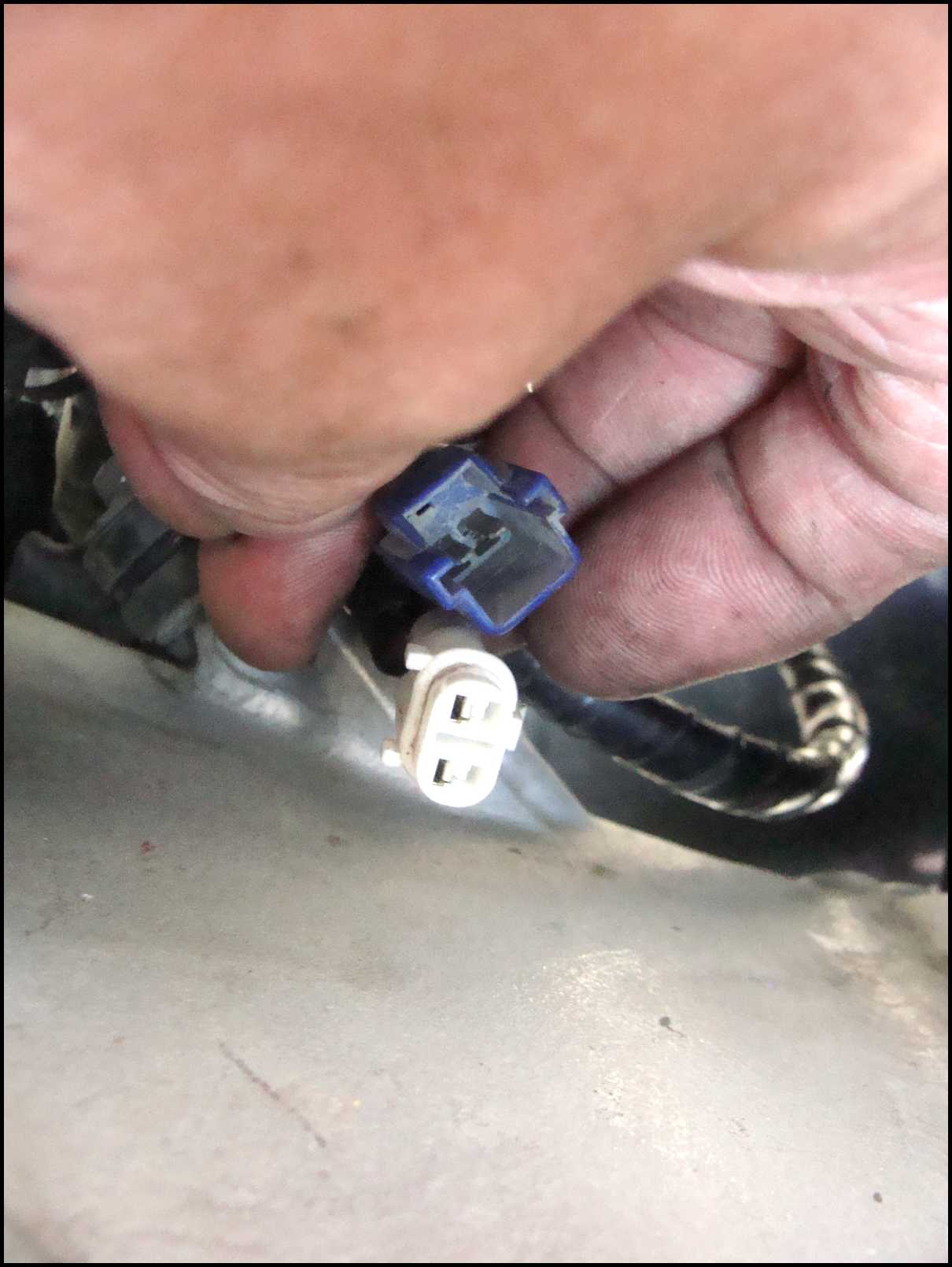
I think I found the heated grip connector - a white 2-wire connector - does it look like this? If so, no VDC either side, engine running.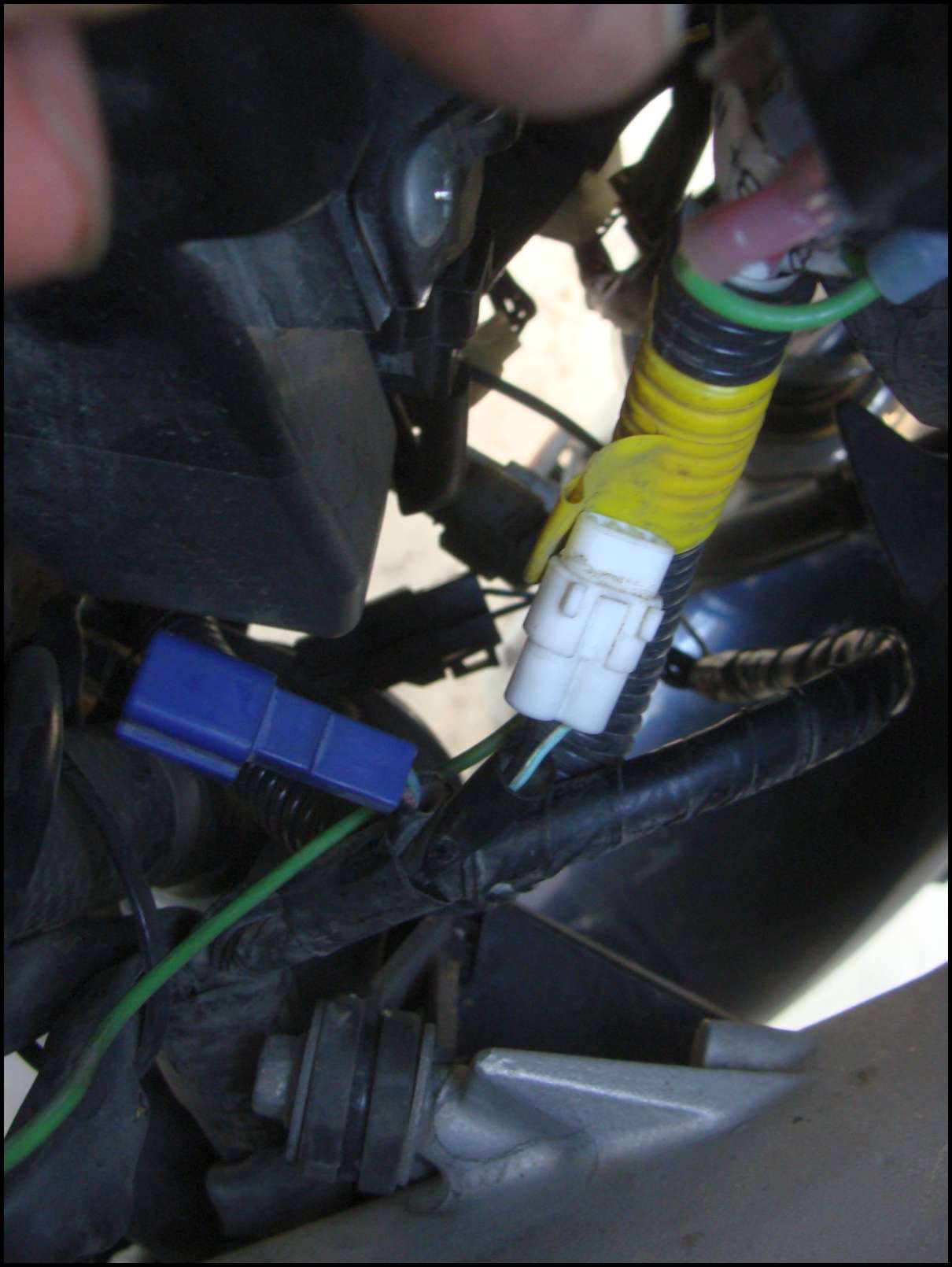
Next to it was this guy - what's it for?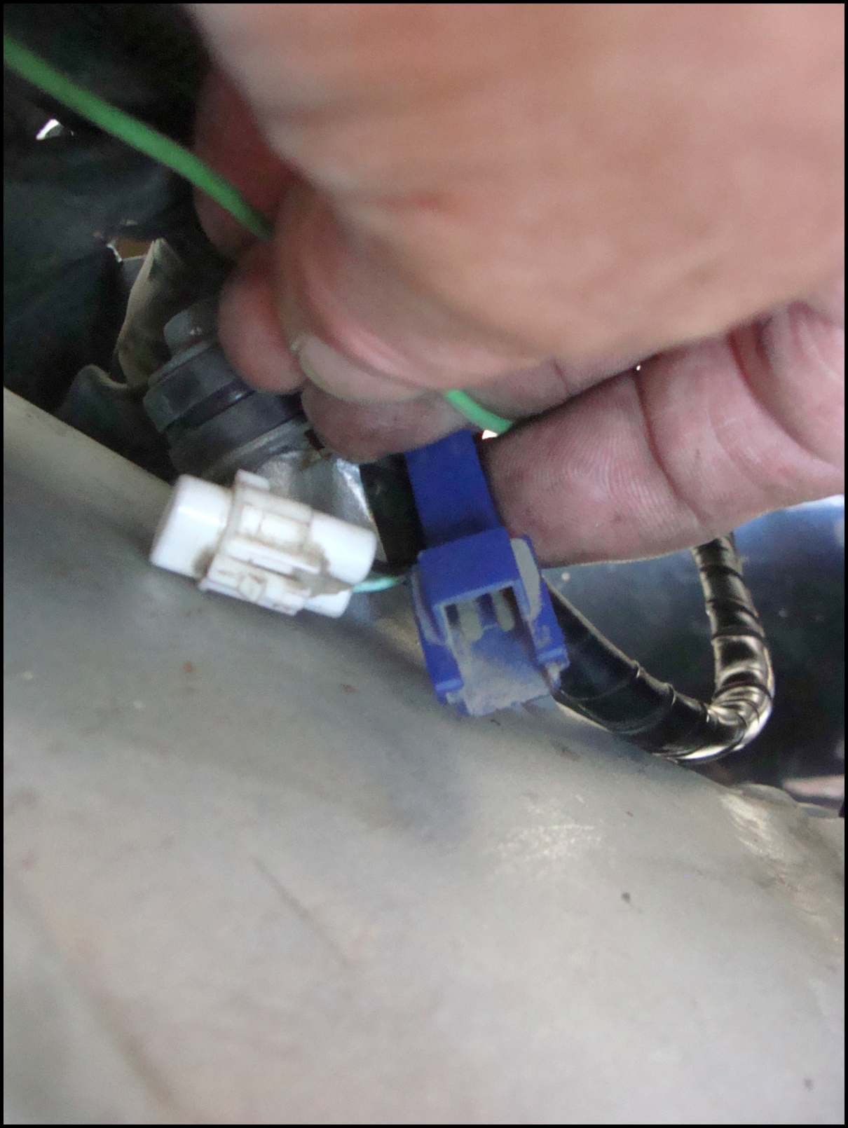
I did find other relays, and for the relationship game (the one you are looking for is just to the xx/yy of the one you found, hopefully)..
Brake relay, right hand side, ahead of battery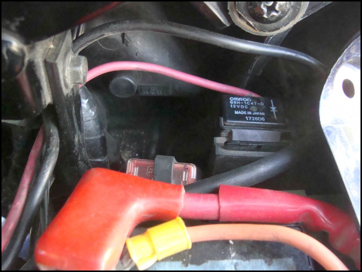
Turn signal/Emergency relay, RHS, left of battery, mounts to tab on headlight inner frame.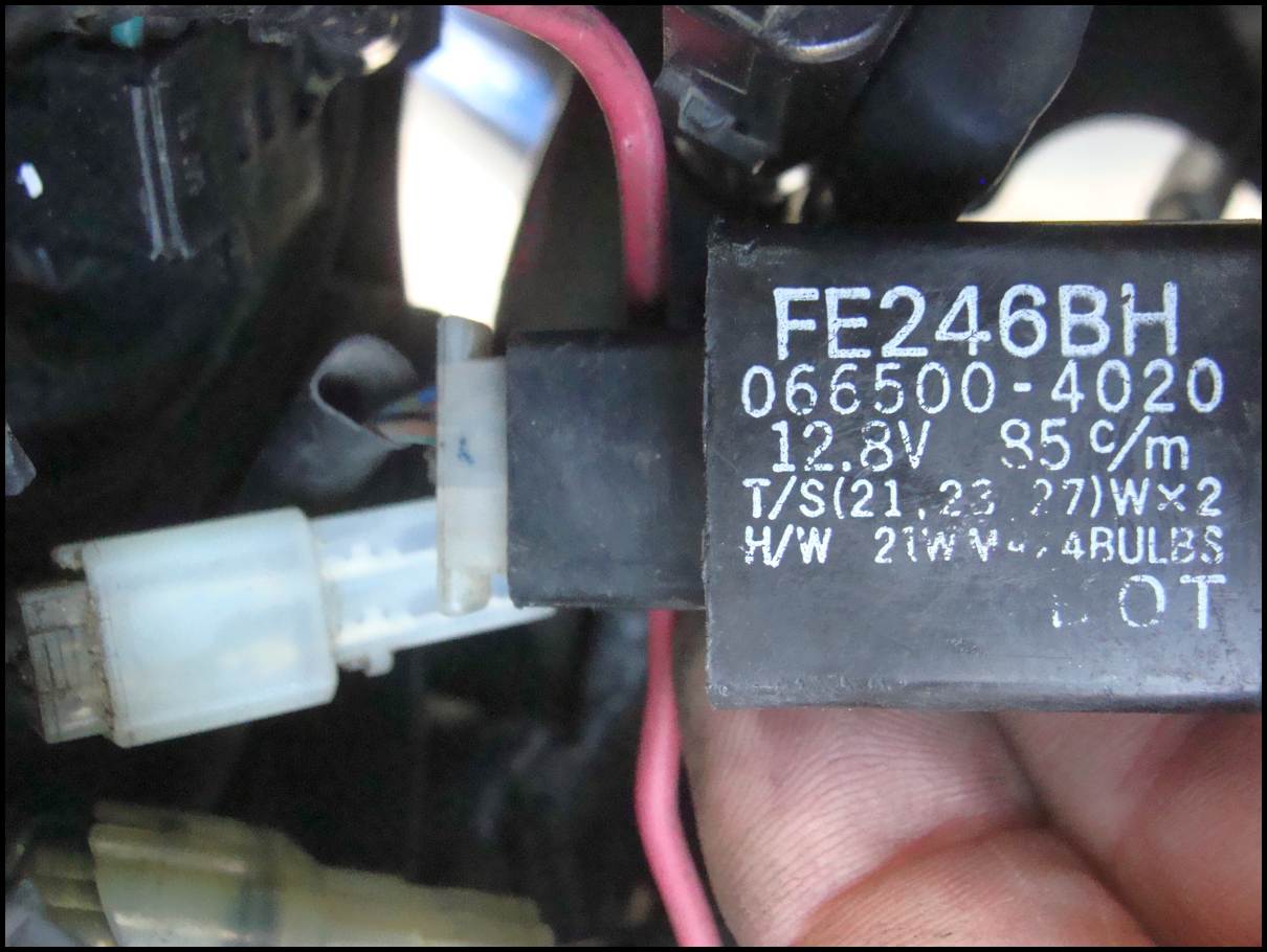
Hi/Lo beam dimmer switch relay, left hand side.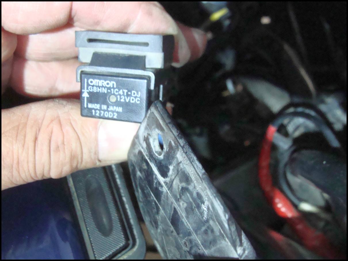
...but what I'm looking for, the headlight relay, I don't see! 
Does anyone have a pix or suggestions where to look for the 'MIA' relay?
Wow, what a long strange trip it's been. I'm very happy KrZy8 decided to have a caniption fit here at home and not on the NERDS run. What a good gurl, barf in the backyard, not in front of company! 
When all is said and done, I am going to document with greater clarity all Gen2 relay locations and identifying markings for future reference..
------
Posted 27 September 2011 - 09:07 PM
I have both my FJR's stripped of all body work so if you need a pic of something let me know. I dunno where the damn relay is ?
Posted 27 September 2011 - 09:20 PM
That means the windshield and its stuff has to come off, the fairings have to come off, but first the handy-dandy "whadda-they-do?" vent panels have to come off. Hell, find kaitsdads gen II fairing and Cowl thread in the FAQ section.
Posted 28 September 2011 - 04:54 AM
dcarver, on 27 September 2011 - 07:34 PM, said:
...When all is said and done, I am going to document with greater clarity all Gen2 relay locations and identifying markings for future reference..
There are two 2 pin blue connectors in the Gen II, I'm 99% sure that the connector in the picture is the side stand connector. The heated grip blue connector will have Red/Black and Green/Blue wires. I only suggested this connector because it may be easier to get to than the headlight relay. If the headlight relay is indeed on the battery box then you may be able to just go directly to the relay.
You would think that we should be able to identify all the relays and switches from the service manual wouldn't ya 
It seems that the Gen II has had more relay failures than the <insert angel harps> Gen I <harps off> have had.
The tip-over switch is under the seat on my Gen I, right next to the seat latch bar. Looking down on the switch I can read the 'this side up' arrow.
------------------
Posted 28 September 2011 - 08:10 PM
Following IonBeam's suggestion, located clicking sound to just under RHS inner cowling sub fairing.
Really?
Could this be true?
Removed the plastic inner piece and Oh My!
Two relays, dangling from secured ty-raps, available for me to look at!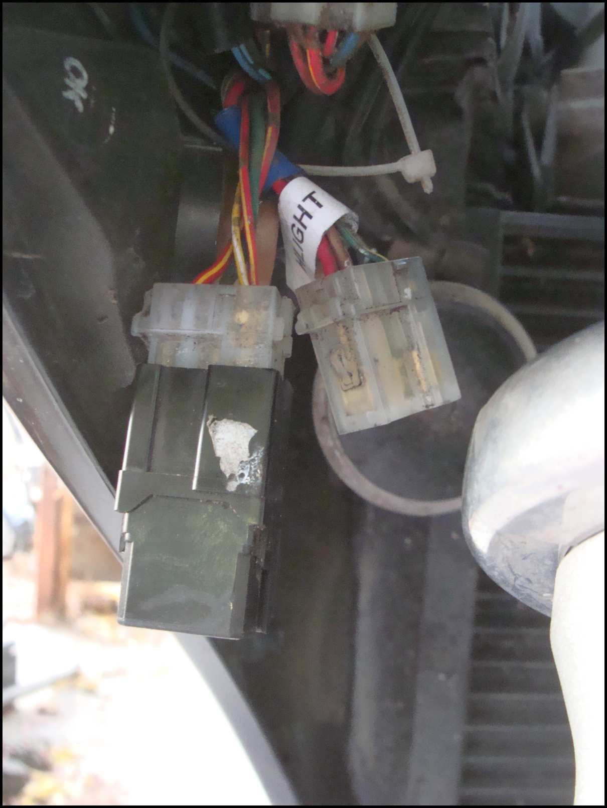
Looking at this, I realized that my bud Ivan, at Hidden Power Cycle Clinic, was totally responsible for 'relocating' these relays to an 'accessible position' after my deer strike.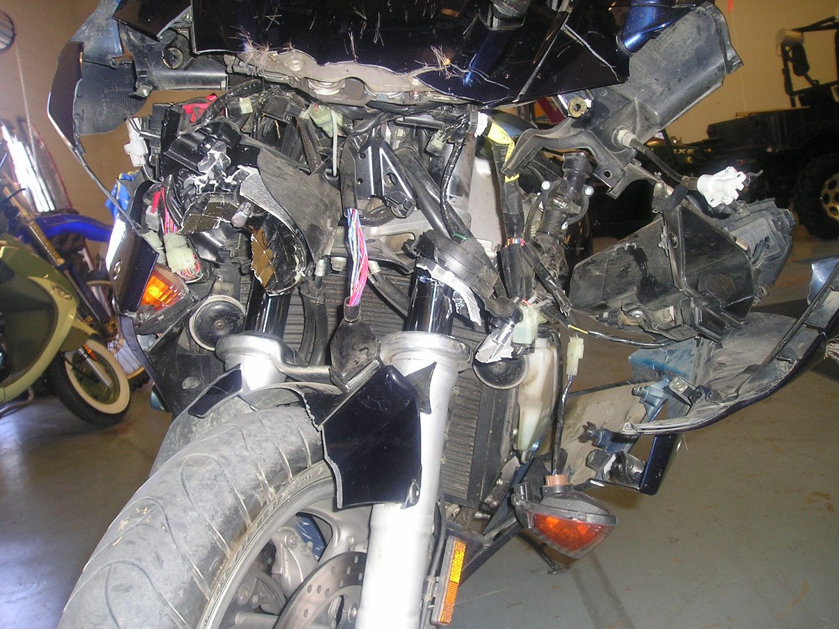
That's what I like from a *practical* tech.. moving stuff from the assembly line to where it can be accessed later without 5 hours of labor charge! Woot-Woot!
Looking at the two relays, wondering which one was what -
decided to jump the power leads of the first one - and the fan came on.
OK then, incorrect labeling by me on the relay.
Removed both relays, they are the same. (Fan and Headlight)
Swapped Fan for Headlight, fired KrZy8 up and Woo-Hoo! Lights.
Switched relays to confirm diagnosis -
yes, true.
Tapped 'bad' headlight relay with appropriate density tool, and, *voila* lights.
OK then, problem solved.
So happy I don't have to remove all the plastic to access 'factory installed relay'.
..and yes, I will be researching alternative relay mfr's as the one from MammaYamma do not appear to be all that 'stout'..
Ideas?
Comments?
Thanks again to the forum and peeps for helping out -
Sincerely,
dcarver n' KrZy8
Posted 29 September 2011 - 06:48 AM
wfooshee, on 29 September 2011 - 05:35 AM, said:
I was surprised to read that the relay(1) clicked! I'm not sure that Don has arrived at root cause yet. As Walter points out, the socket and wiring may still be suspect. Note that the big relays which are directly actuated by the ECU have a diode across the coil and any replacement relay should have a snubbing diode either internally like the OEM or have one added externally. There is a pretty good chance that the headlight relay is in fact good and corrosion on the relay's contact power pin has been broken. IMO, the relay should be mounted so that it is solid and unable to bounce or move. IMO, the rubber strap thingie that Yamaha uses is a good thing to have because it dampens high frequency vibrations.
(1) The relay is made up of a coil and a set of contacts. The coil is wound to form an electromagnet. The contacts of automotive relays are sometimes 'reed' types with long flexible shafts tipped with high current 'buttons' and sometimes a mechanical pivot or slide with the contacts held apart by a spring. Usually the loud clickers are the pivot and slide type. When 12 volts and ground are connected to the coil it produces a magnetic field which pulls the reeds or pulls the pivot/slide closed. The high current contacts slamming together cause the CLICK. To produce a CLICK the relay coil and contact mechanics have to be working. The only way a CLICKING relay can be bad is if the high current button(s) were burned from arcing. Any other failure would mute or prevent the CLICK.
----------------
RossKean, on 29 September 2011 - 07:01 AM, said:
Most small current, non-automotive relays are constructed differently and the click they make is the coil and ferrous part coming together. In automotive grade relays the contacts have to be strongly forced together in a rigid fashion so the contacts don't bounce of vibrate open under normal driving conditions. To achieve this the switched part of the relay is heavy and strong which produces its own CLICK to go along with the coil and ferrous part that also clicks.
------------
Posted 29 September 2011 - 07:48 AM
ionbeam, on 29 September 2011 - 06:48 AM, said:
wfooshee, on 29 September 2011 - 05:35 AM, said:
I was surprised to read that the relay(1) clicked! I'm not sure that Don has arrived at root cause yet.
wfooshee, why wouldn't the relay click when triggered by diagnostic test 52?
ionbeam, same question?
It's not a loud click by any means, but I could easily hear the actuation and feel the vibration too. FWIW, it's the same failure symptoms I had earlier with the hi/lo relay, and that relay is protected from elements much better than the power relay. Bench testing the hi/lo relay, with a rear brake light bulb as load, when actuated, the relay would pass just enough current to dimly light the filament. Tapping the relay resulted in full current and brightness.
Both male and female pins looked clean, dry, corrosion free on the power relay. Wiggle-Waggling connector wires had no effect. Tapping the relay resulted in actuation. Replacing the suspect relay with the fan relay resulted in consistent headlight operation, multiple tests. I'm pretty sure it's a failed power relay and the issue is bad contacts (corroded/burned/whatever) - want me to break out the Dremel and dissect it?
---------------
Posted 29 September 2011 - 08:18 AM
dcarver, on 29 September 2011 - 07:48 AM, said:
ionbeam, same question?
...when actuated, the relay would pass just enough current to dimly light the filament. Tapping the relay resulted in full current and brightness...Replacing the suspect relay with the fan relay resulted in consistent headlight operation, multiple tests. I'm pretty sure it's a failed power relay and the issue is bad contact...want me to break out the Dremel and dissect it?
Usually a failed relay will have an open coil or failed contact mechanism; without these parts working the relay will not make a sound.
I believe that you have indeed found the root cause and it is the relay. The dim filament and swapping with a known good part sews it up. In my discussion of relays I mentioned that about the only way a relay can make a solid click and yet not work is if there is a contact failure. Your description of symptoms fits this scenario exactly. So would a corroded power pin in the connector, but you say the all look good.
Yes, by all means do an autopsy! Don't spare the gore. You have taken some awesome macro pictures, time for more here.
dcarver, on 29 September 2011 - 07:52 AM, said:
1. when connected via rubber boot to hard part (frame, headlight stay, etc)
2. or when dangling from wiring loom?
In my non-techie CrestonCowoy mode, I'd almost guess less vibration hanging from the nice vibration damping effect of a wire absorption device? 
Take a thin strip of metal and flex it back and forth repeatedly. Notice the 'work' heating? Keep going... eventually you will have two pieces of metal in your hands. Hold the harness wires still and start flexing the relay back and forth. As the wires flex remember what happened to the metal strip. The most susceptible place will actually be where the wire and connector pin are joined.
----------------
Posted 29 September 2011 - 08:49 AM
Panasonic relay from Mouser

Cheap enough at $3.53...
Posted 29 September 2011 - 09:33 AM
dcarver, on 29 September 2011 - 08:49 AM, said:
Panasonic relay from Mouser
Cheap enough at $3.53...
Good find. The coil resistance of this relay is a bit higher than the stock Omron relay G8H-1C4T-D which is favorable. This relay has a higher Drop-Out voltage than the OEM, which could be unfavorable, but in this application the difference doesn't matter. This relay also has a built-in snubber so the diode is taken care of. Overall, this Panasonic relay is a direct replacement. Just be sure you order the correct pin layout (dimensions).
Even though the upper right corner of the data sheet says Discontinued as of August 31, 2010 Mouser still shows stock available.
Note that Matsushita is now Panasonic.
-----------
dcarver, on 29 September 2011 - 10:51 AM, said:
Is it better to find the Omron?
No.
=========================================================================
In the manufacturing of anything there is a Bill Of Material (BOM) that specifies what parts are to be used to build the various assemblies and sub-assemblies. Almost every part in the BOM will have at least one alternative part number listed which is a direct substitute. At the time that Yamaha does the purchasing to buy the parts needed to build FJRs some items may be out of stock, have excessively long lead times or there may be a big price advantage to buying a direct substitute. If you look at the FJR's BOM or any documentation it will show one P/N from one manufacturer, but they may well have installed a different P/N from a different manufacturer.
My Gen I manual calls out for the Radiator Fan Relay and Headlight Relay to be a ACM33211 M05 (Omron)! The FSM uses the Matsushita P/N but calls out Omron as the manufacturer  which is an error. Your Gen II manual specifies Matsushita ACM33211 M05. One of your pictures clearly shows the Omron G8H-1C4T-D part in your bike. The Matsushita ACM33211 M05 is a 96.0 Ω coil relay. The Omron relay is a 80.0 Ω coil relay and since that is the part I saw in your picture I assumed that this is the part that Yamaha has been installing in spite of what the FSM lists for a P/N.
The coil resistance difference is petty trivial. At 14 volts one part draws 0.175 amps - 2.45 watts and the other part draws 0.152 amps - 2.13 watts. The coil current will make a difference in the contact pull-in strength and contact clamping strength. The Fan and Headlight relays are a high current part and 80.0 - 96.0 Ω coils have about as high a resistance as you can get and still hold the contacts together tightly enough to keep the contact resistance in the 0.15 Ω range.
----------
Posted 06 October 2011 - 08:01 AM