- Home
- Forums
- Ride Reports
- MotoBikes
- Restorations
- Wrenching
- 1963 BMW R69s
- 1969 BMW R60/2
- 1978 Yamaha 125
- 1979 KZ1300
- 1979 Kz1300 - Bob's Beauty
- 1981 CBX SuperSport
- 1981 Kz1300 Model A3 - Chocolatie
- 1984 Ford F250 XL
- 1987 ATK
- 1987 MowieMowie
- 1987 RotoTiller
- 1988 Honda Accord Lxi
- 1990 BMW RT100 - Barrie
- 1991 Harley Davidson FLHTCU
- 1992 Johnnie Deere
- 2000 YZ426
- 2002 Dodge Ram
- 2006 Carson RacerX Trailer
- 2006 Host Camper
- 2006 KrZy8
- 2007 Wabs
- 2012 KTM 690R
- 2013 Naomi - FJR 1300
- 2014-08-01 Air Compressor - Sears
- 2017 Kioti
- 2018 Toy Hauler
- 2020 Honda Fit
- 2021 Miscellaneous
- 2024 Log Splitter
- 2024 NeoDyne MC Lift
- 2050 test
- Lil Trlr
- Eats
- RIP
- PC Not
- Cages
- Test
- FJRF Best
- For Sale
Candy Butt Association
World's Wimpiest Riders

Theme by Danetsoft and Danang Probo Sayekti inspired by Maksimer
2012-08-28 Audiovox CCS 100 troubleshooting
From FJRForum.com
FJRForum: Audiovox CCS-100 cruise control installation - FJRForum
Jump to content
2 unread notifications
Signed in as dcarver 2 New
2 New
Audiovox CCS-100 cruise control installation Sharing installation ideas
#1 FJRCarShopGuy
Posted 28 January 2007 - 10:44 PM
Hello fellow FJR owners,
It was suggested that I should post my documented Audiovox Cruise Control installation on my 06 FJR1300A under its own thread. Ive had some requests to post the highlights and areas of interests of my install. You will see below that some areas have deviated from previous installs. Ive made some changes to streamline and or to minimize modification to the factory stuff. I hope this will help to assist those who are interested in installing the Audiovox CCS-100.
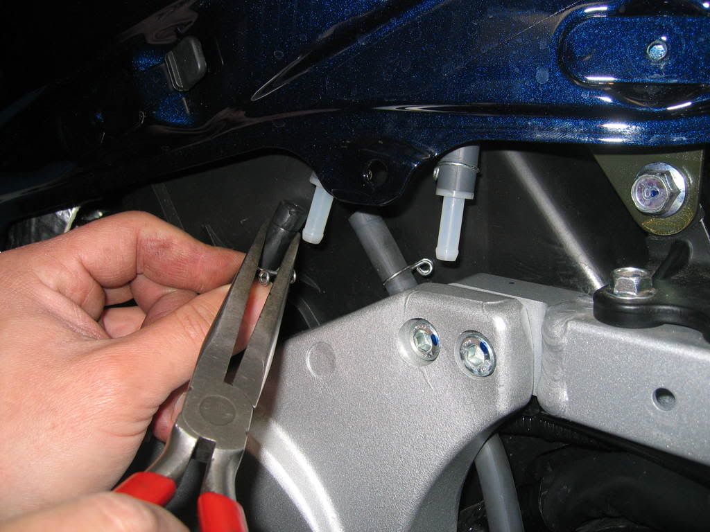
In order to remove gas tank, you will need to remove two vent hoses on the left side.
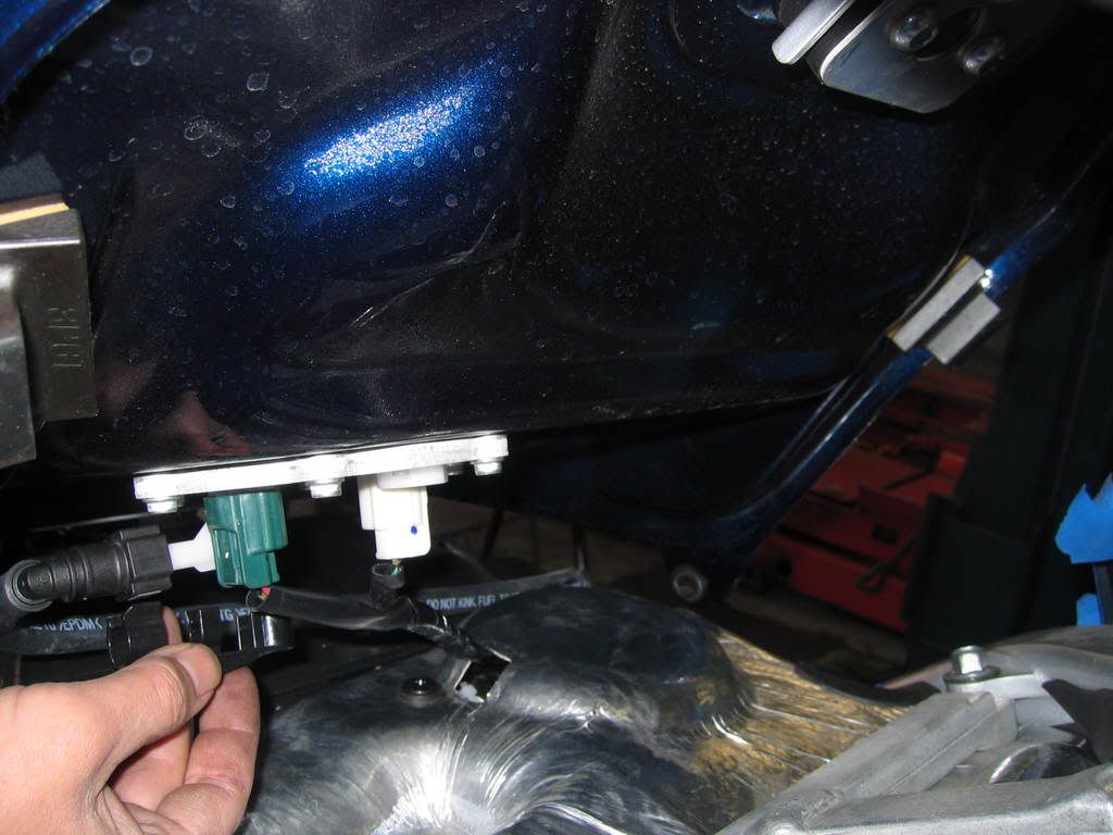
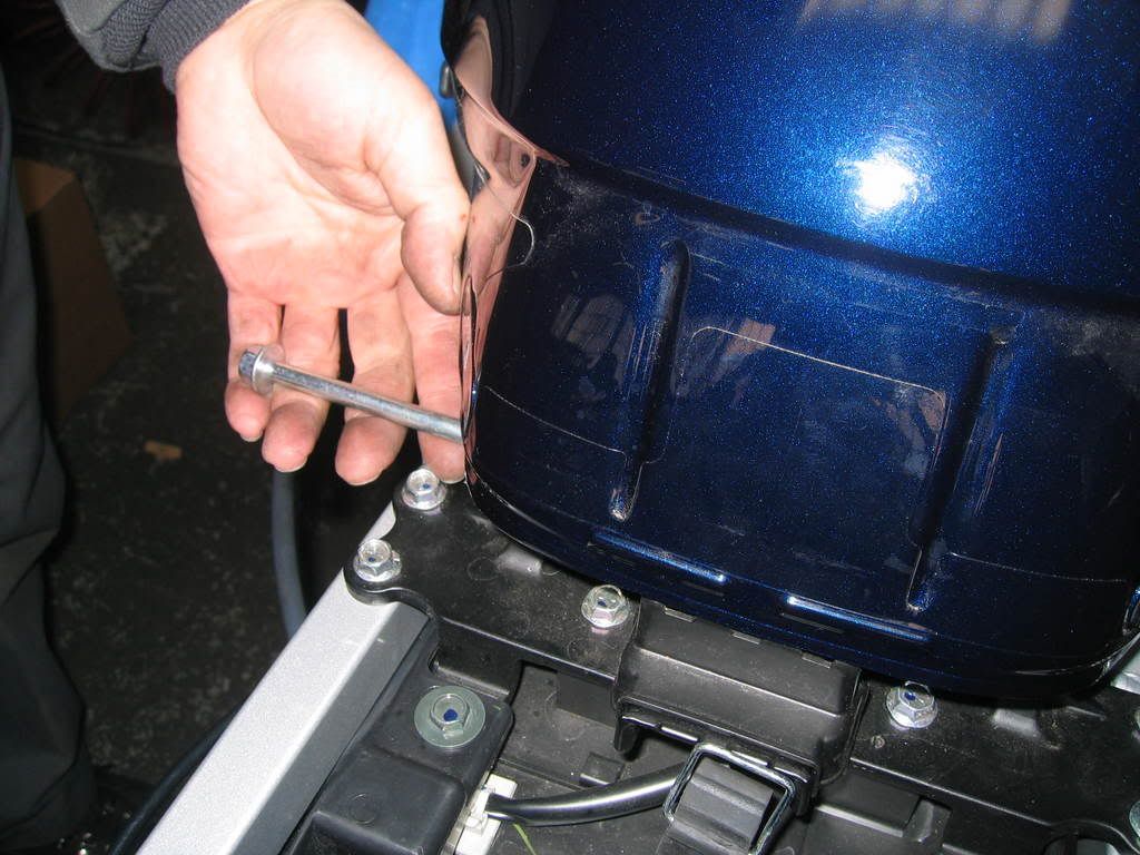
Remove allen bolts in front of gas tank and loosen nut and thru bolt in back of gas tank. Do not remove thru bolt at this point, this will help you to tilt the tank in order for you to remove electrical connectors and fuel line. Notice the plastic fuel line safety securing piece that need to come off first before fuel line can be removed.
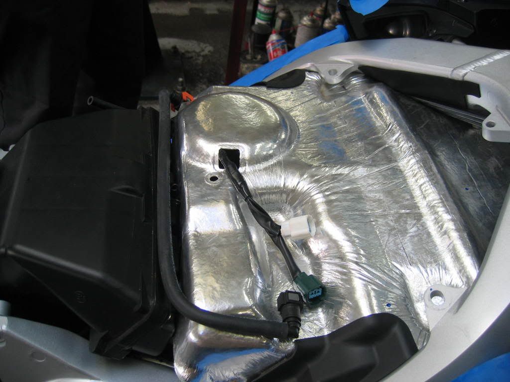
This is what you see with tank removed.
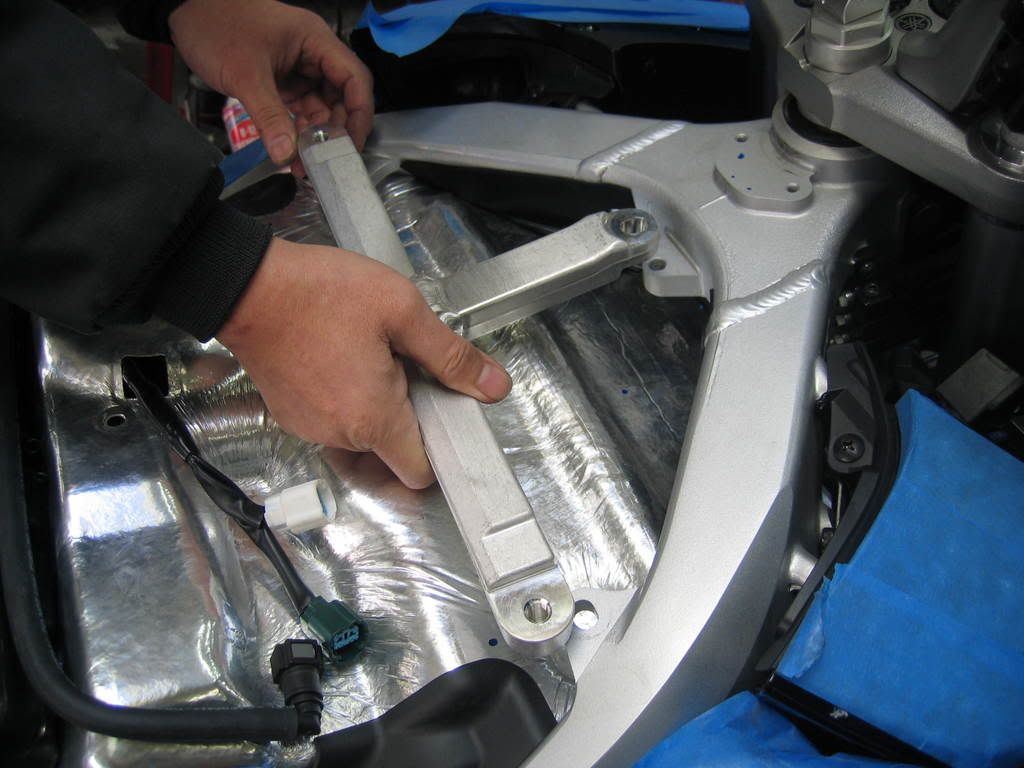
Remove 3 bolts and frame brace.
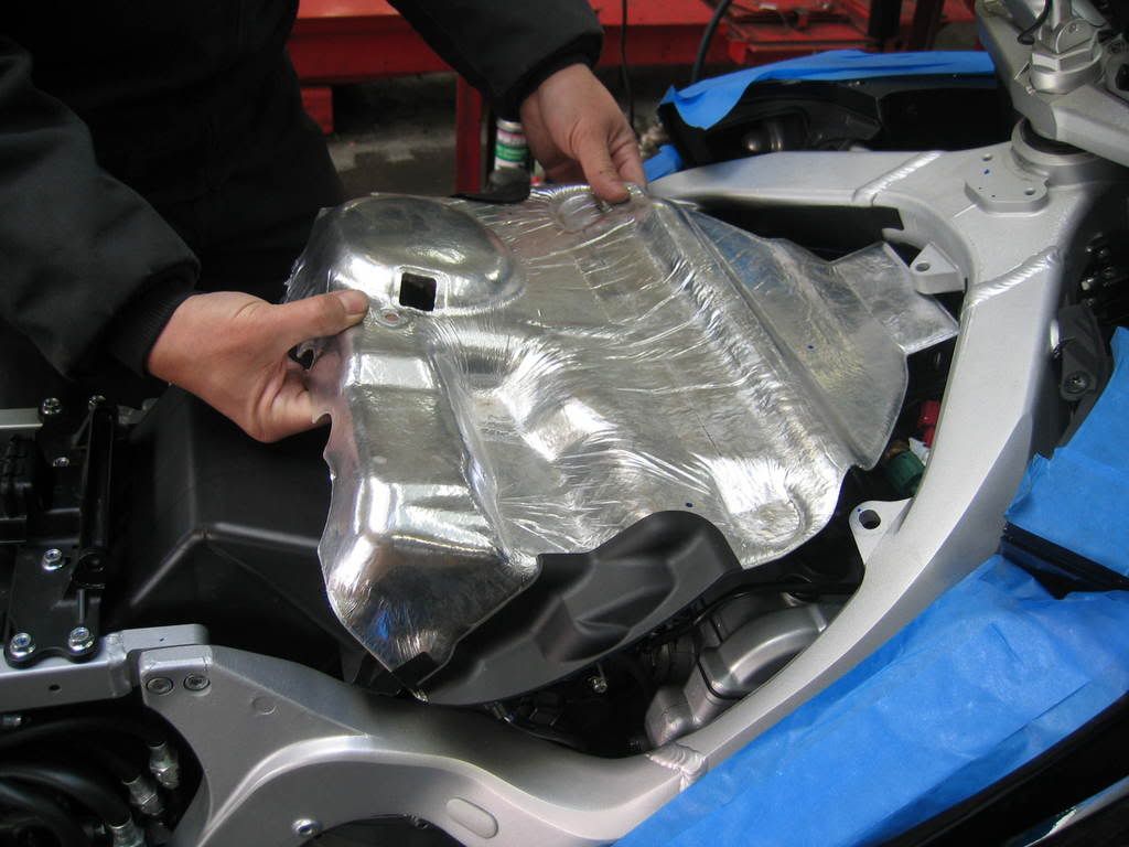
Remove heat shield.
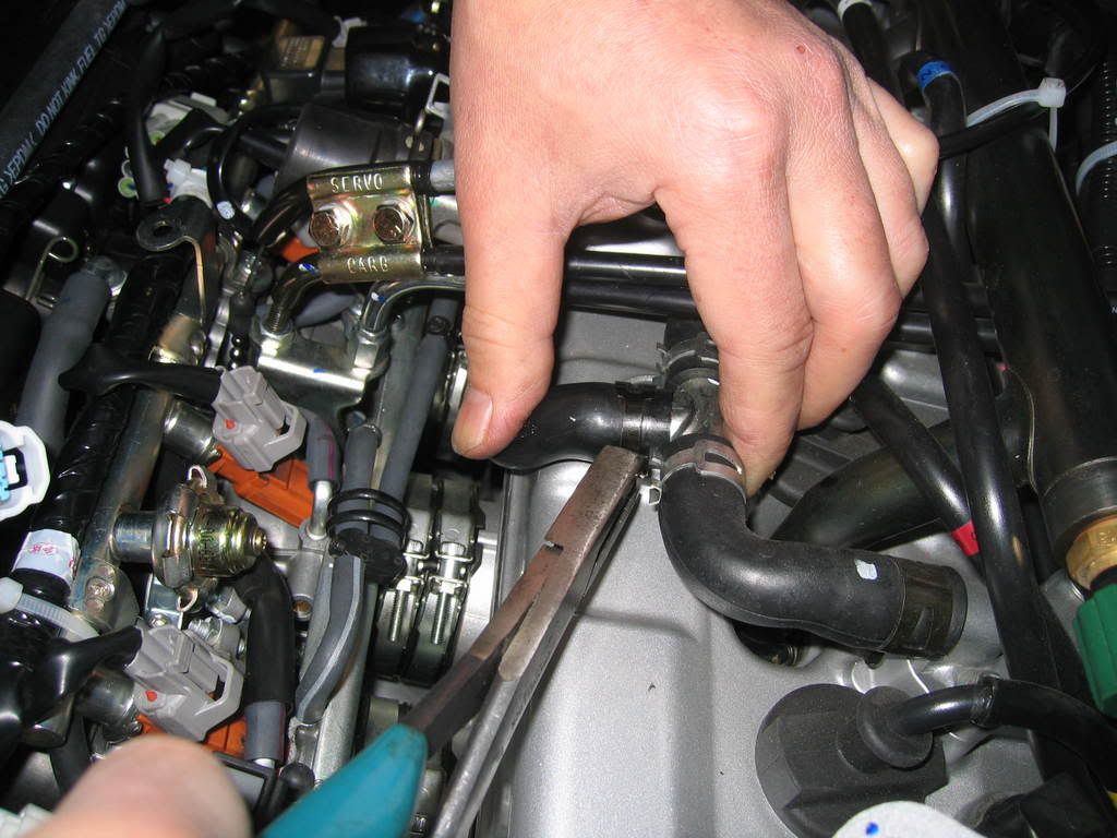
Remove air valve by loosening 3 hose clamps and electrical connector.
Disconnect idle speed adjustment cable from retainer grommet located below right front frame between engine and frame.
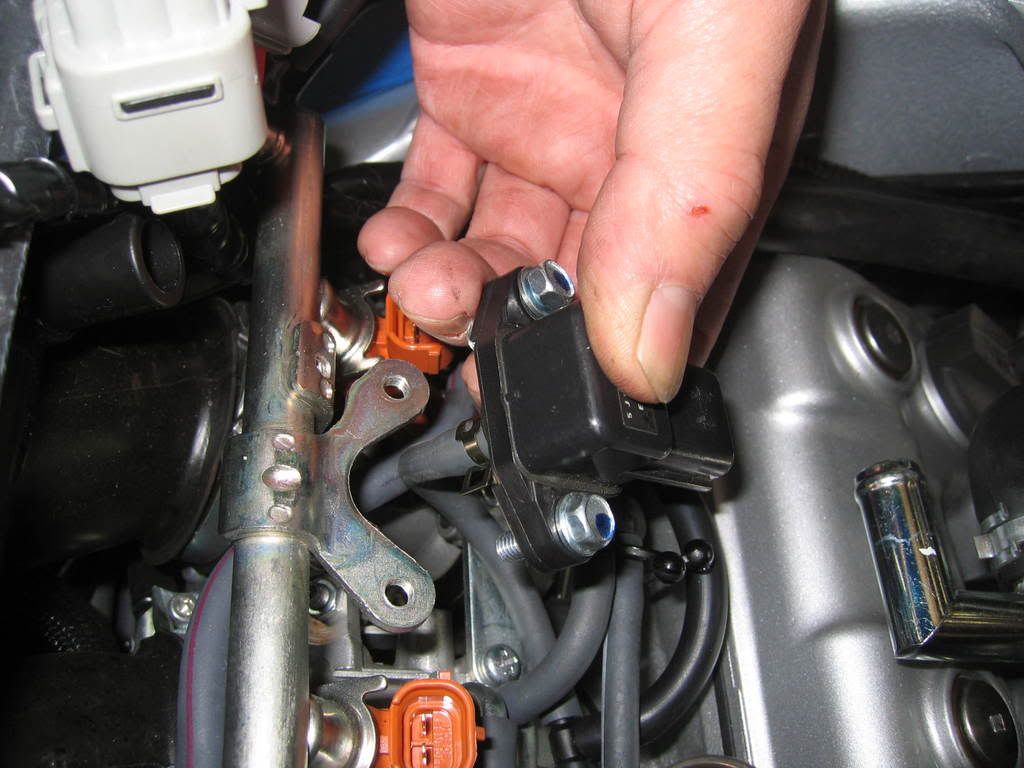
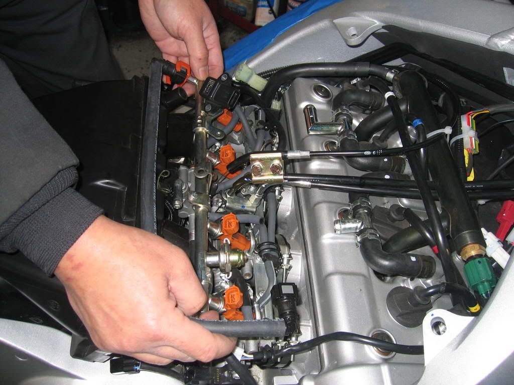
Remove 2 bolts to the fuel system MAP sensor off the injector rail.
Disconnect electrical connector to Injectors, MAP sensor, Throttle position sensor etc and move entire harness to left side of the bike and out of the way.
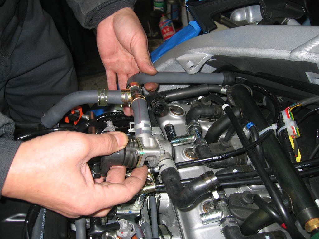
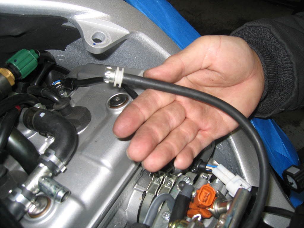
Disconnect vacuum hoses from fuel rail assembly.
Remove 2 screws and spacers securing fuel injector rail. These screws are tight, I had to use an impact driver in order not to damage them.
Remove fuel injector rail with injectors, be careful not to drop the o rings at the tips of the injectors.
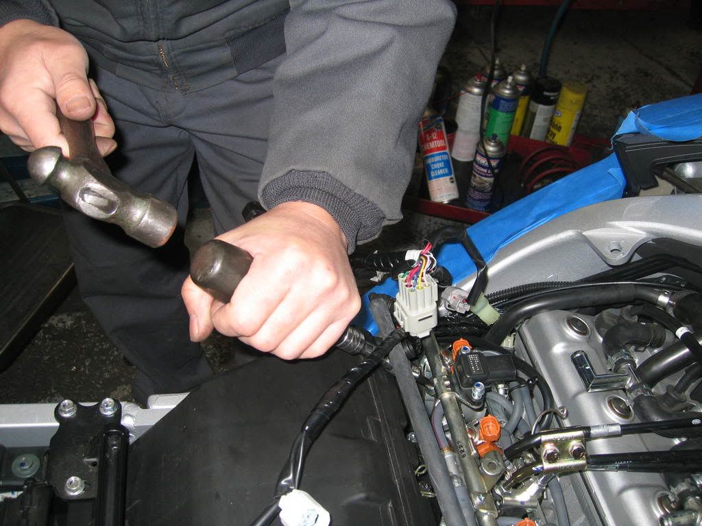
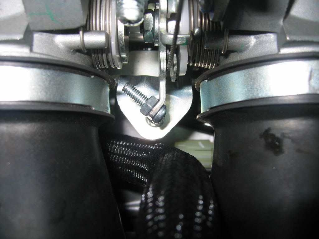
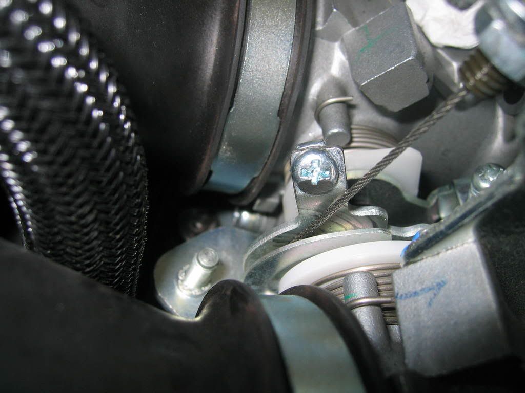
Drill hole for 4 mm bolt to install on throttle pulley tang and install bolt and nut with lock tight. I used a spring loaded auto center punch to put a nice dimple onto the tang so my drill bit wont wander. Do not use a regular center punch with a hammer here, you will bend the tang and it will not be aligned with the idle speed adjusting screw after. This is a small hole with little material to work with. You dont want to drill off center here. Take your time, it may be helpful to have somebody hold the throttle open to a position for a straight shot with the drill.
Use a low profile button head allen bolt to avoid touching and or hanging up on the factory throttle cable, the clearance is very tight. Test this many times to be sure!!!!!!
As you can see from the pictures below, I did not use a button head allen bolt because I did not have one. Instead, I ground away a portion of a 4mm Phillips screw for this reason. You could do this as well, just be precise. FYI, Smitty has the correct bolt and he was nice enough to offer one to me but I was too impatient to take him up on it.
Prepare the servo unit for installation: (sorry I dont have pictures for the next few steps)
1) Remove the 2 screws holding the access cover in back of the servo unit and remove cover.
2) Remove main wiring harness. Note what position it came off. Although theres a locking tang, it does not look totally fool proof.
3) Cut off and discard the separate harness (wrapped together) grey and black wires. Only cut the wires that are wrapped together and not the bigger black wire in the main connector of the servo unit harness. This is only used for vehicles with VSS (vehicle speed sensor). Since we will be operating on engine speed only (tach signal) this will not be needed.
4) Set the 7 dip switches inside the servo unit as follows: #1, #4, #7 in ON position. #2, #3, #5, #6 in OFF position.
5) Reinstall main connector and resecure cover. Make sure wires are spread out in order to have good seal.
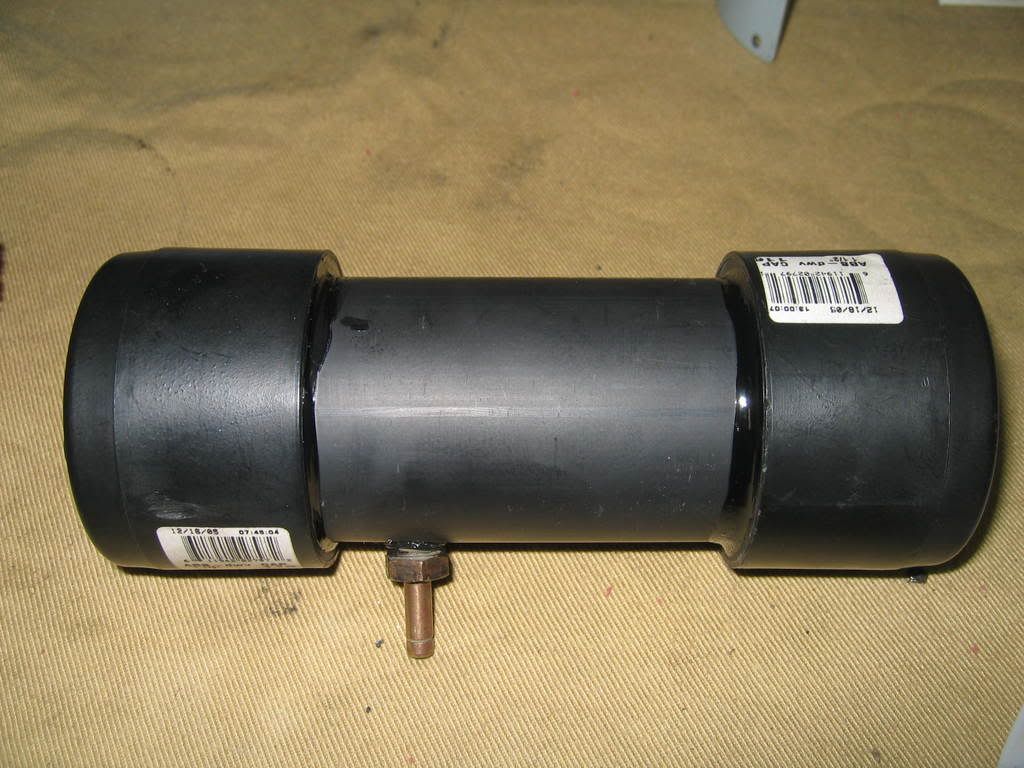
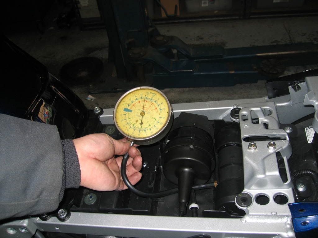
Fabricate vacuum canister: I used 1 ½ ABS drain pipe with end caps and a brass fitting. All available from your local Home Depot or Lowes.
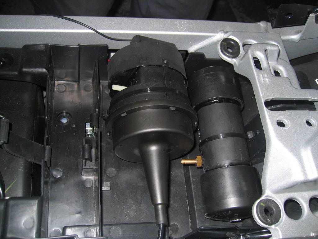
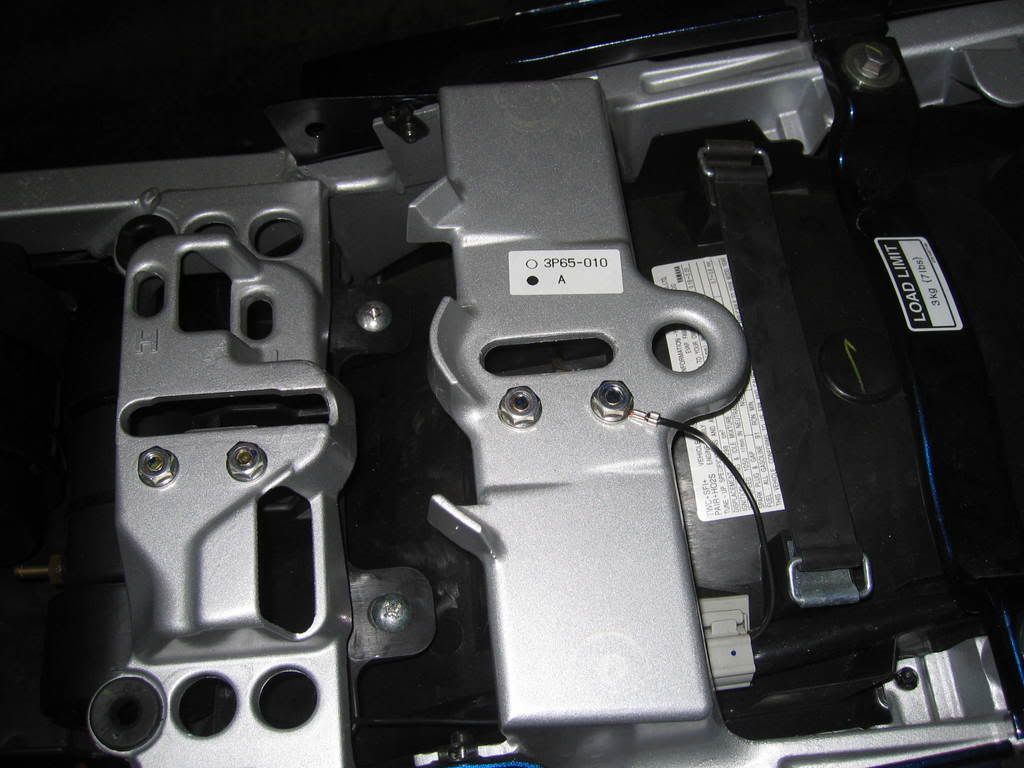
Prepare storage tray for servo unit and vacuum canister: Notch the right side for the servo unit to sit properly. Drill small holes to accept tie straps to hold both units in place. Be careful here, the computer is mounted under tray. I removed the entire tray to avoid any chances of damaging computer. Secure servo unit and vacuum canister. Route the cable along left side of frame and back down center of engine toward throttle pulley.
I made a cable guide sleeve to reduce the steep angle between the end of the servo cable to the throttle pulley. I used a piece of hard plastic automotive fuel line and used a heat gun to soften it for the bend. It fitted perfectly over the metal threaded cable end.
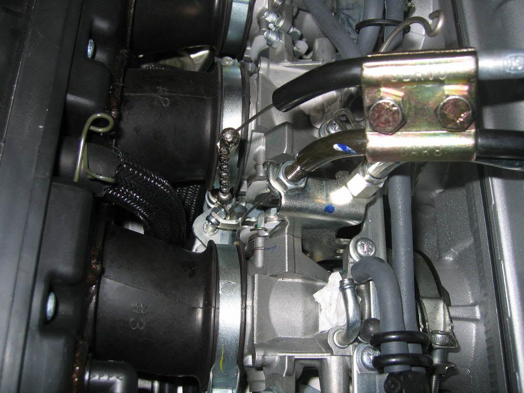
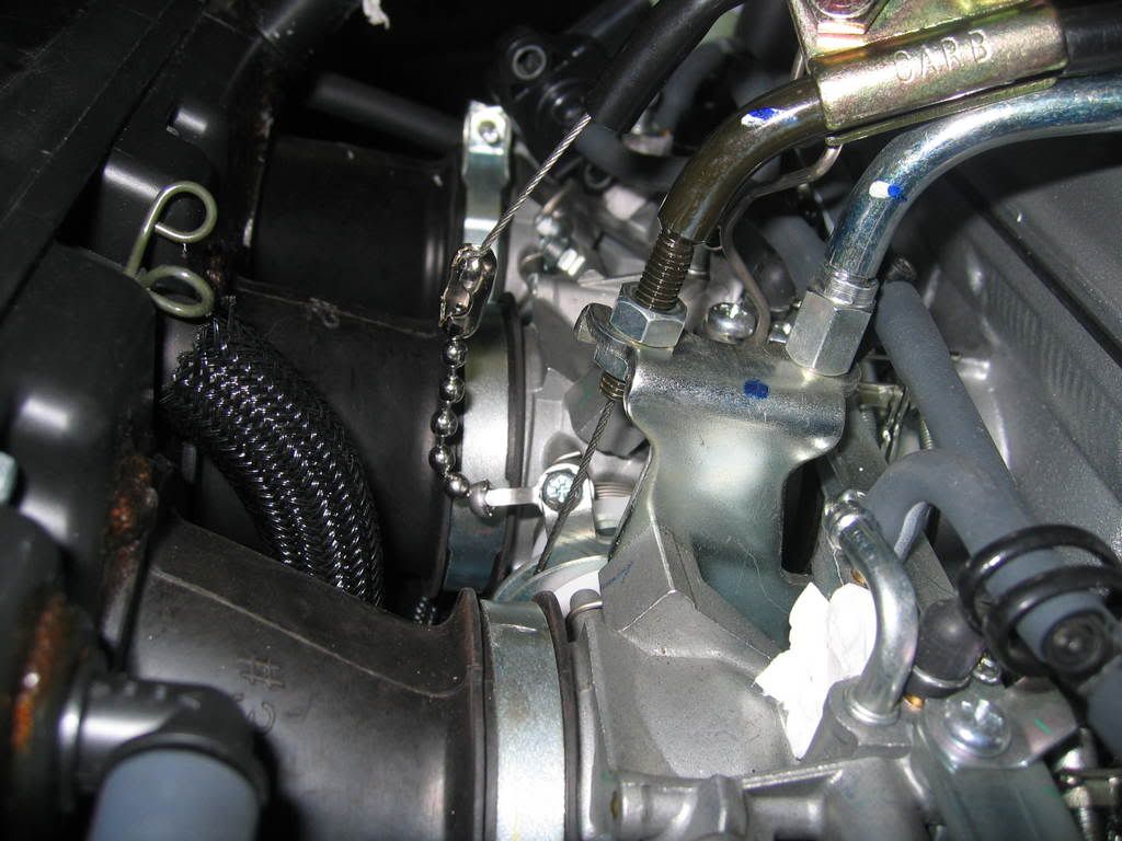
Cut off 7 bead of the chain and attach connectors to both ends of the chain. I used a small piece of shrink tubing over the servo cable connector after crimping as an extra precaution (its not in this picture).
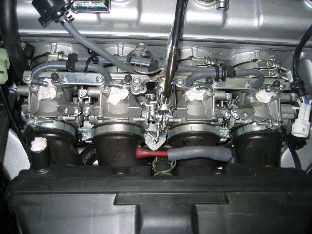
Attach cable to throttle pulley bolt by using 2 nuts with lock tight compound.
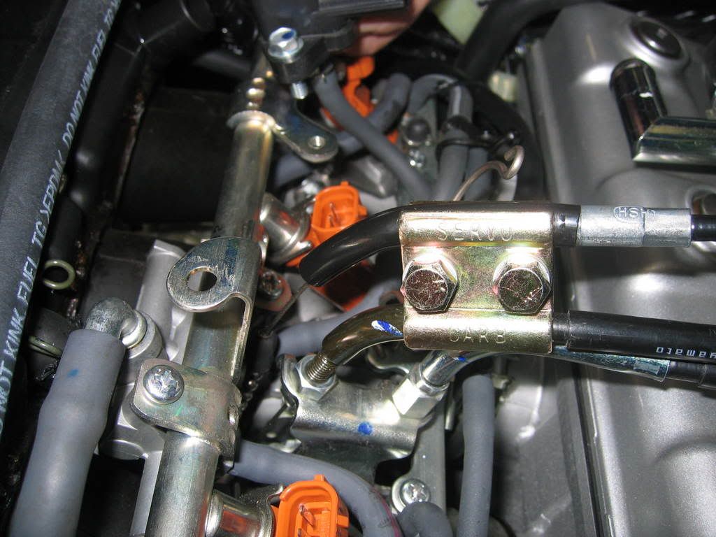
Secure cable with supplied bracket. You will need to adjust the position for best fit and cable free play after installing the injector fuel rail and other surrounding components.
Operate throttle and make sure cable/pulley combination will clear all surrounding parts without any hang ups. This is very very very important!!!!!
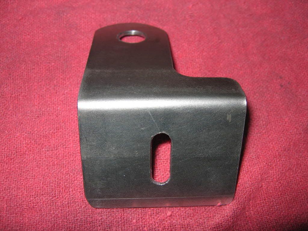
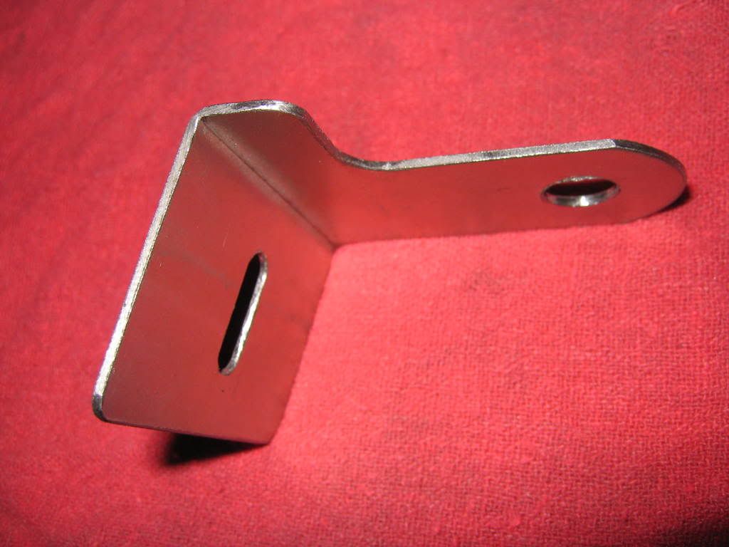
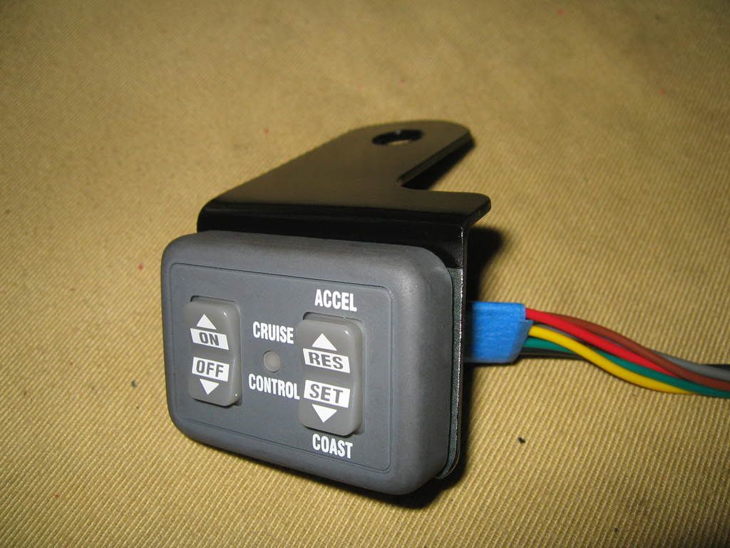
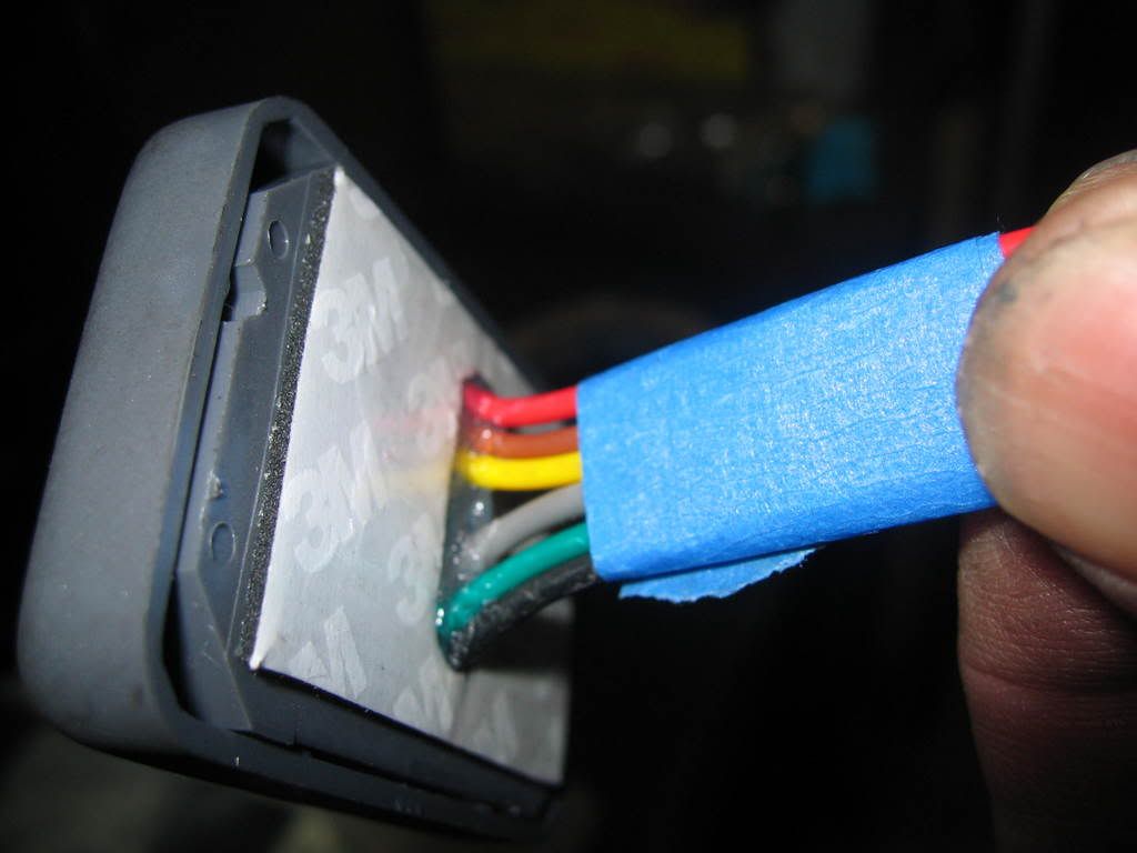
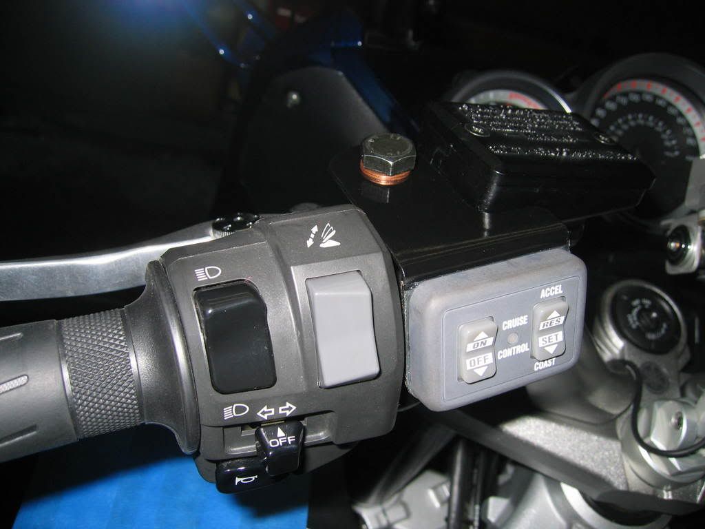
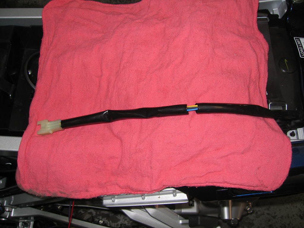
Control switch panel wiring and mount: Skyways mount looks very nice, but I decided to make one like Smittys. I put silicone sealer at the wiring opening first and then around the opening after it was secured to the bracket. The black and grey wires are for the back lighting of the panel, the grey wire was designed to tap into a light circuit so it would light up when lights are turned on. I tied it into the red wire which is the power feed, this will cause the panel lights to stay on at all times no harm done and I didnt have to cut into the factory wiring. The black wire simply gets grounded to a good ground source, I found a good place on the left side brake line bracket near the steering head. I used shrink tubing to insulate the entire harness before inserting the 4 pin terminals into the white connector.
Mount the switch panel assembly and follow factory wiring routing thru opening into front of engine compartment.
Route the green, yellow, brown, blue wires from the servo unit toward front of the bike following cable on the left side. Use wiring conduit to protect wires. The green, yellow and brown wires are cut to length and soldered back together, then the pin terminals are installed into the white connector matching colors to the control switch panel.
Power feed connection: The red wire that comes attached to the 4 pin connector with a 3 amp fuse and inline fuse holder is the power feed wire. I decided to do away with this fuse assembly and used the factory #12 fuse instead. This is for the 12 volt power adaptor located in the left compartment. I only use this for my GPS/PDA which draws very little currant so it should have no problems supporting the cruise unit as well.
I removed the fuse assembly from cruise unit, soldered a wire to length to reach #12 fuse and attached it with a scotch lock connector. This is the only scotch lock connector of the entire install. I had no choice because the length of the wiring exposed on #12 fuse was minimum. It would have been difficult to solder here. See picture.
#2 FJRCarShopGuy
Posted 28 January 2007 - 10:54 PM
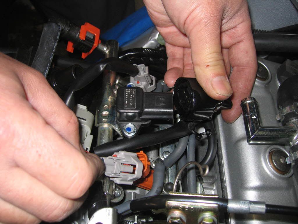
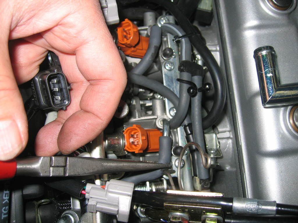
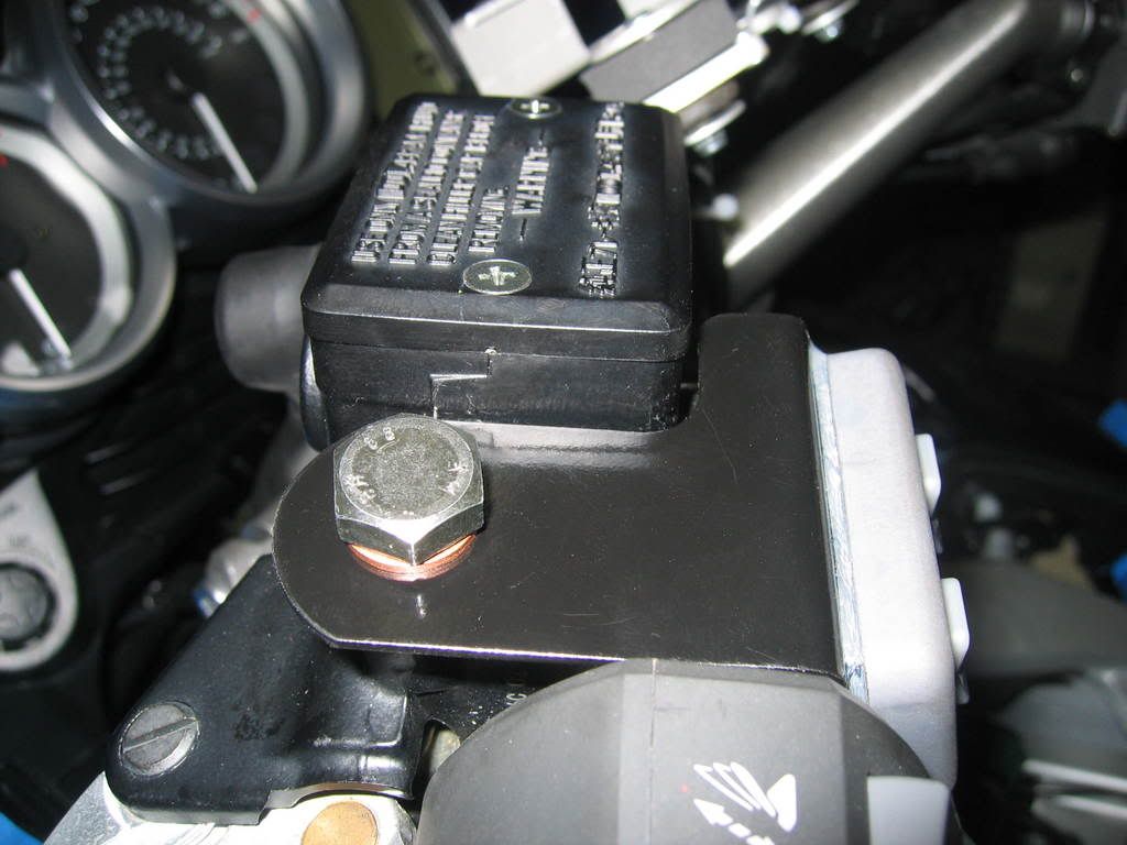
Tach signal: I didnt want to cut into the ignition coil primary wire so I made an adaptor harness by soldering a female and a male terminals with shrink tubing insulation. I didnt want to chance the bike running on two cylinders if this wire were to fail.
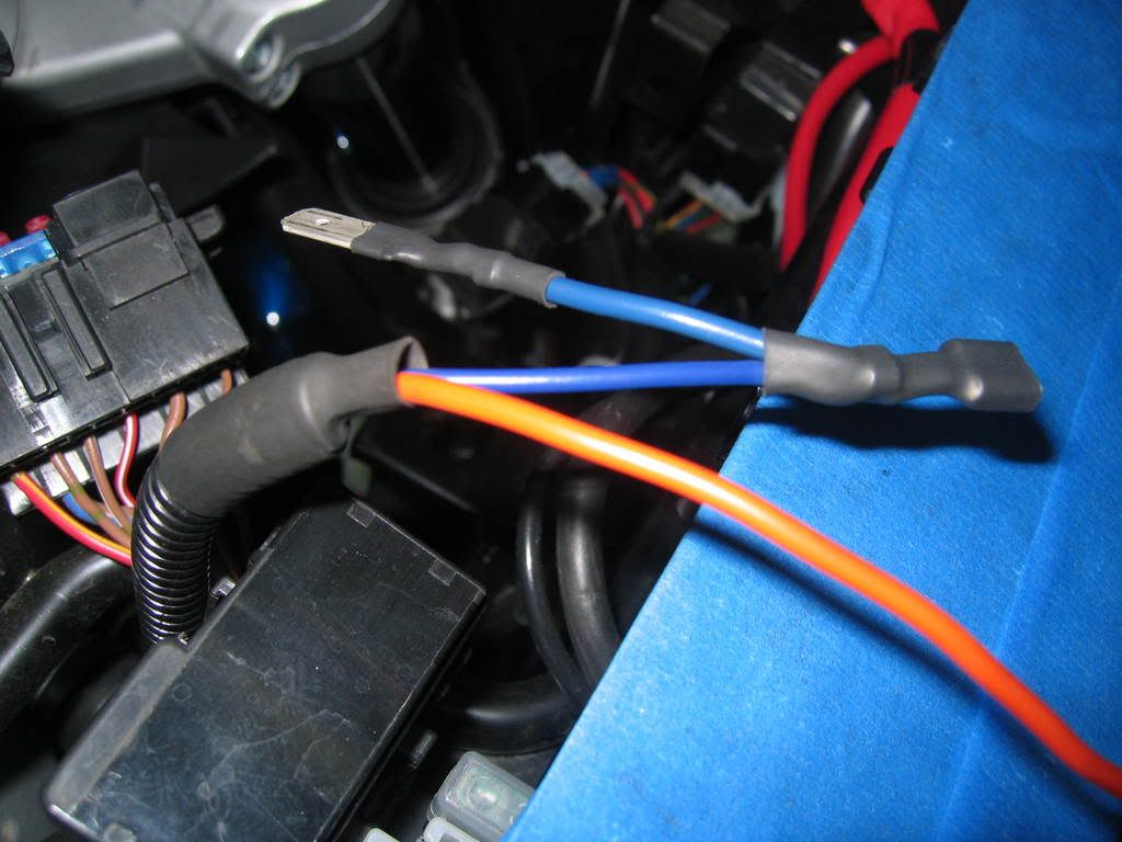
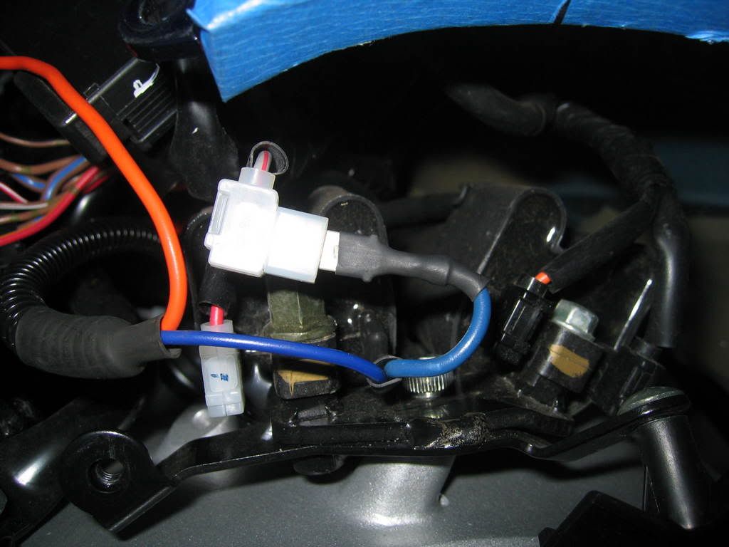
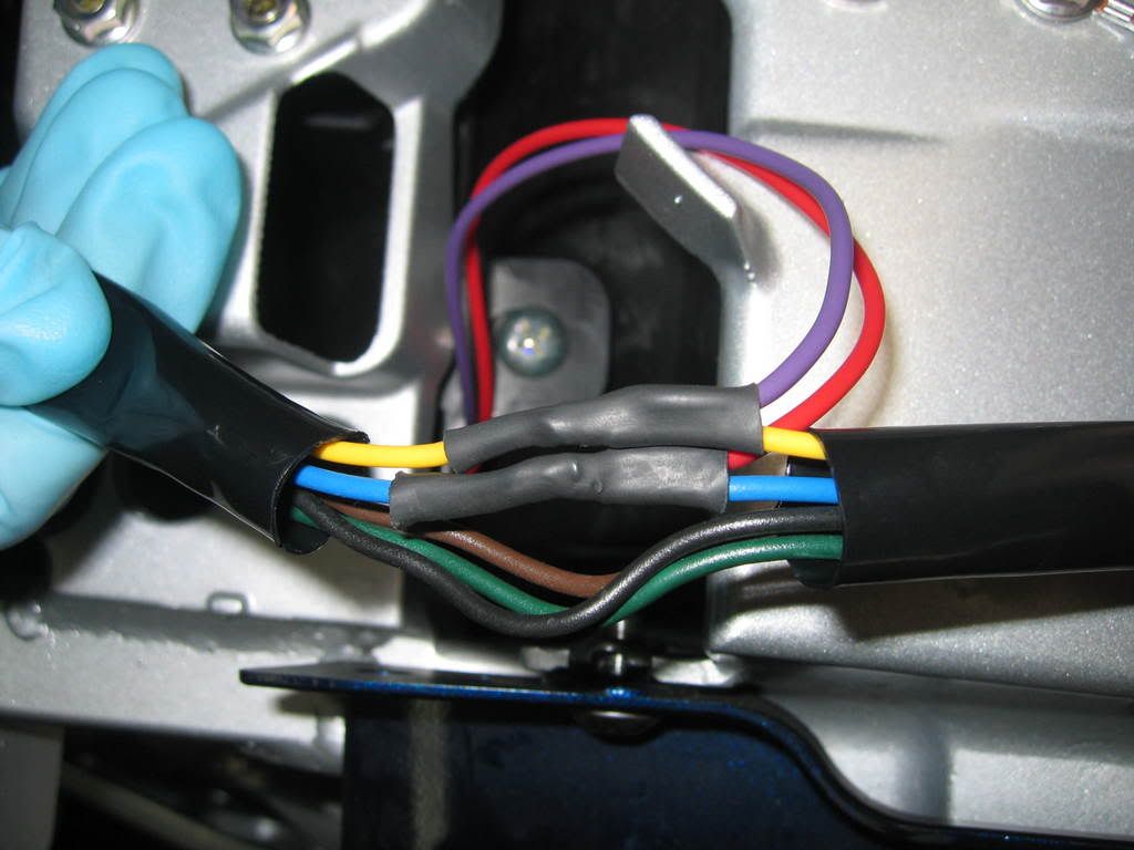

The factory grey with red tracer wire is connected to the male terminal and the female terminal is connected to the coil. No cutting or modifications done to factory wiring. Now you can secure and tie down wiring.
Brake/tail light wiring: The purple wire from the servo unit is an important connection. It is hook in parallel to the factory yellow wire at the tail light harness located under the seat. It ground thru the brake light bulb filament when no voltage is present, in order to operate the cruise. When brakes are applied and 12 volts is present, it cancels the ground and shuts off the cruise. This is a safety feature!!!!! Make sure you make a clean and secure connection here. I soldered in this circuit and used shrink tubing to seal the connection. The red wire is hooked in parallel to the factory blue wire which is the power supply for the tail light.
Last wiring connection: The black wire with an eye bolt terminal attach from the servo unit is simply grounded to a good ground source. I used one of the seat lock latch nuts.
vacuum supply and connections: I studied the hoses and vacuum sources and decided to hook into all 4 cylinders without cutting any of the factory hoses. No harm done to have 4 intake strokes in 720 degrees of crank shaft rotation vs. 1 if its hooked into only one cylinder. This will provide a much smoother and stronger vacuum. Located on the left side of the fuel injector rail is the MAP sensor (manifold absolute pressure) it is use to sense engine load for fuel mapping. This is an ideal source because it has to be accurate for fuel management. Simply use T fitting to hook in supplied vacuum hose to servo unit and route hose in the same path as the cable and wiring harness.
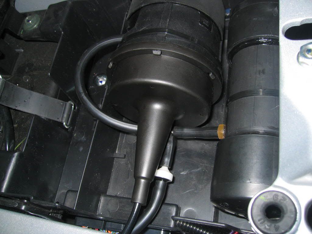
Vacuum connection at servo unit: I used a vacuum check valve from a car (Volvo) interior climate control system. But any good vacuum check valve will work. The purpose is to retain and reserve usable vacuum during up hills or acceleration when manifold vacuum would be low. This way the cruise system has instant vacuum source when it is needed. Study the configuration and notice when vacuum drops it will lock in and retain any developed vacuum. I tested this system to hold about 14 of vacuum with the engine off.
Now you are ready for reassembly. In reverse order, reinstall all parts removed. You may need to adjust the servo cable position after fuel injection rail is installed for clearance and free play. There should be a slight amount of play in the beaded chain, make sure theres no tension.
Good luck on your install, any ideas, thoughts or suggestions are welcome. Please feel free to contact me with any questions.
Gordon,
Fellow FJR owner
#3
Community Forum Sof
AudioVox CCS 100 Manual (pdf)
Clicky Me for the Manual
and wiring diagram
AudioVox Solenoids
2012-08-29 Notes of Caution
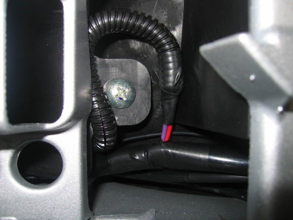
it's the wire with the red piece of tape in the middle of it
was quite a head scratching, frustrating experience over days and many redo's to figure out what was wrong. It won't stay engaged without that diode.
2012-08-29 Things to Consider
Audiovox Cruise Control for 06-07 FJR, problem solved, maybe?


If you have a properly installed AVCC that works at first and then fails this may help.
After a year of frustration I now have a working cruise control on my 2007
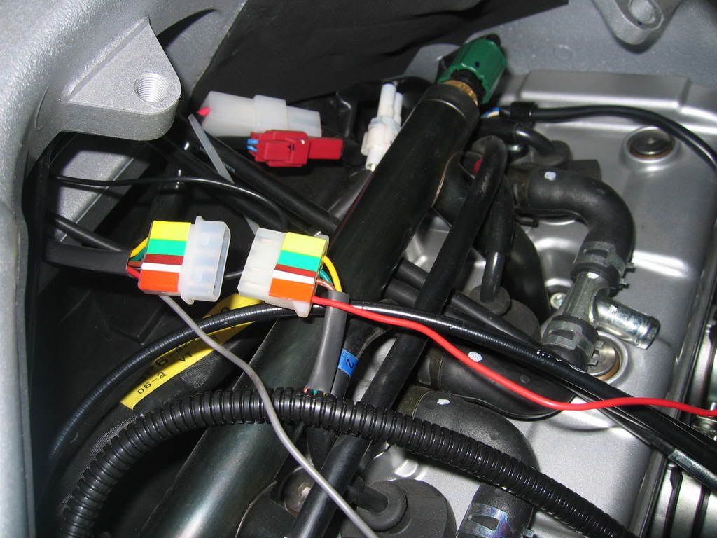
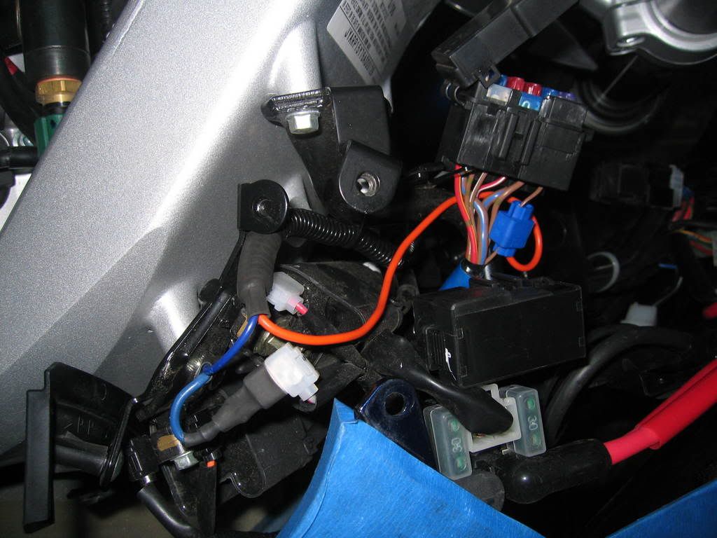
Summary: Shortened AVCC blue wire connected to the orange wire near the ECU plug and servo DIP switch #7 set to OFF for ECU source.
I have made 3 rides >50 miles in 80 degree temps at 75+ mph and it worked perfectly. I live in the flat lands of coastal South Carolina and will not be able to test more extensively with long distance and long climbs until early June.
I think that moving the servo blue wire from the coil to the orange harness wire, #1 on the connector, under the left side cover (where you do the Barbarian Mod) and setting the #7 DIP switch to OFF are the most important changes.
I think that the magic is in moving switch #7 to OFF. However, I don’t think if I would move DIP switch #7 to OFF unless I moved the blue servo wire to the orange #1 wire at the ECU harness. I just don’t know what would happen.
You can make your own call on this. It has not let the magic smoke out yet, but it might.