- Home
- Forums
- Ride Reports
- MotoBikes
- Restorations
- Wrenching
- 1963 BMW R69s
- 1969 BMW R60/2
- 1978 Yamaha 125
- 1979 KZ1300
- 1979 Kz1300 - Bob's Beauty
- 1981 CBX SuperSport
- 1981 Kz1300 Model A3 - Chocolatie
- 1984 Ford F250 XL
- 1987 ATK
- 1987 MowieMowie
- 1987 RotoTiller
- 1988 Honda Accord Lxi
- 1990 BMW RT100 - Barrie
- 1991 Harley Davidson FLHTCU
- 1992 Johnnie Deere
- 2000 YZ426
- 2002 Dodge Ram
- 2006 Carson RacerX Trailer
- 2006 Host Camper
- 2006 KrZy8
- 2007 Wabs
- 2012 KTM 690R
- 2013 Naomi - FJR 1300
- 2014-08-01 Air Compressor - Sears
- 2017 Kioti
- 2018 Toy Hauler
- 2020 Honda Fit
- 2021 Miscellaneous
- 2024 Log Splitter
- 2024 NeoDyne MC Lift
- 2050 test
- Lil Trlr
- Eats
- RIP
- PC Not
- Cages
- Test
- FJRF Best
- For Sale
Candy Butt Association
World's Wimpiest Riders
You are here
2017-12-26 Fred W Mirror Extension using Furniture Nuts

Forums:
Progress report on the FZ1 mirror Aux Light mounting bracket project.
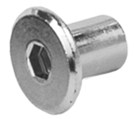
I procured a small quantity (10 each) of some 6mm, internally threaded, "Furniture Connector Cap Nuts" (I'll refer to these as FCCN from here on) in both 15mm and 18mm shank lengths. These would be needed to extend the reach of the studs on the FZ1 mirrors to allow for the added thickness of the Aux Light brackets plus the additional spacers required to clear the recessed mirror mounting area in the 3rd Gen FJR front faring surface.
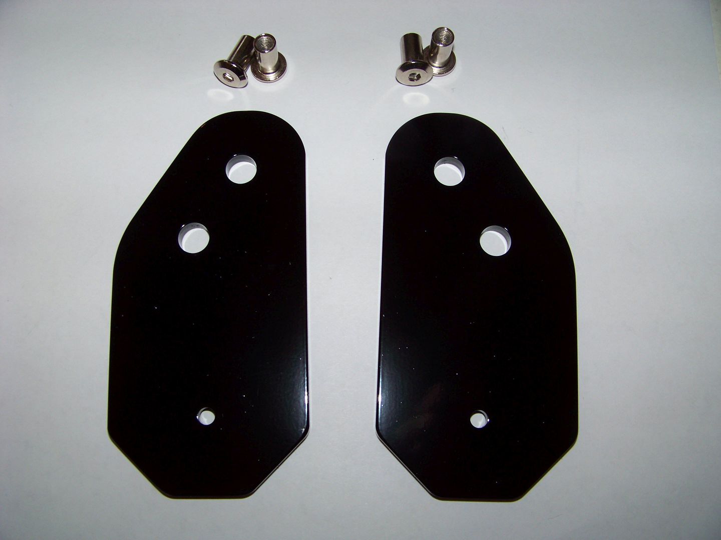
Dave from WynPro (08FJR4ME) sent me a custom made set of his Anti-Vibe Brackets, made completely flat. I gave them a quick couple of coats of rattle can black.
Yesterday, I set out to find out how difficult it will be to get these to work on a 3rd Gen. Here's a reference diagram of the parts of the third gen stock mirror mount:
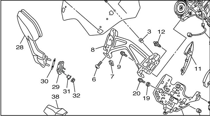
28 - Mirror (doh!)
29 - Plate #1
30 - Plate #2
31 - Collar
32 - Flange Nut
After removing the mirrors, here is what you'll be looking at:
The rubber surface you can see from the outside is just the 3mm thick "Plate #2" (#30 in the parts diagram) and can be easily lifted off and removed. It is just loosely fit onto the two aluminum collars (#31).
Our goal is to remove the two collars from the other half of the rubber mounting, "Plate #1" ( Item #29) to allow room for the new FCCNs to extend up through the frame, faring and rubber mounts. You'll need to do that from the inside.
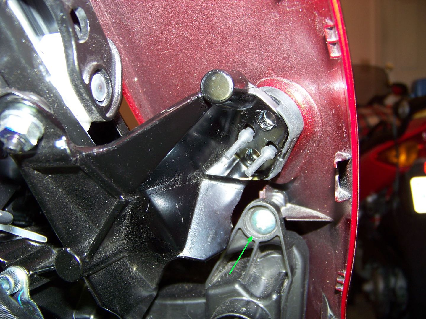
The trick for getting Plate #1 with the two collars removed is to first take out the philips head faring screw indicated above. This will allow you to flex the painted faring away from the subframe just enough to yank the rubber piece out.
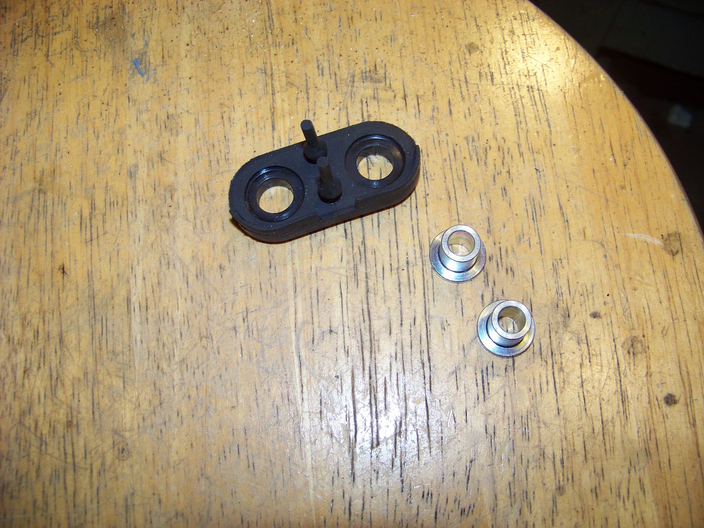
Here is is removed from the bike and the collars removed from the Plate #1. The two nipples are a loose fit in the subframe so it can easily be removed and reinstalled, though its a bit fiddly to get the long nipples threaded back through the holes.
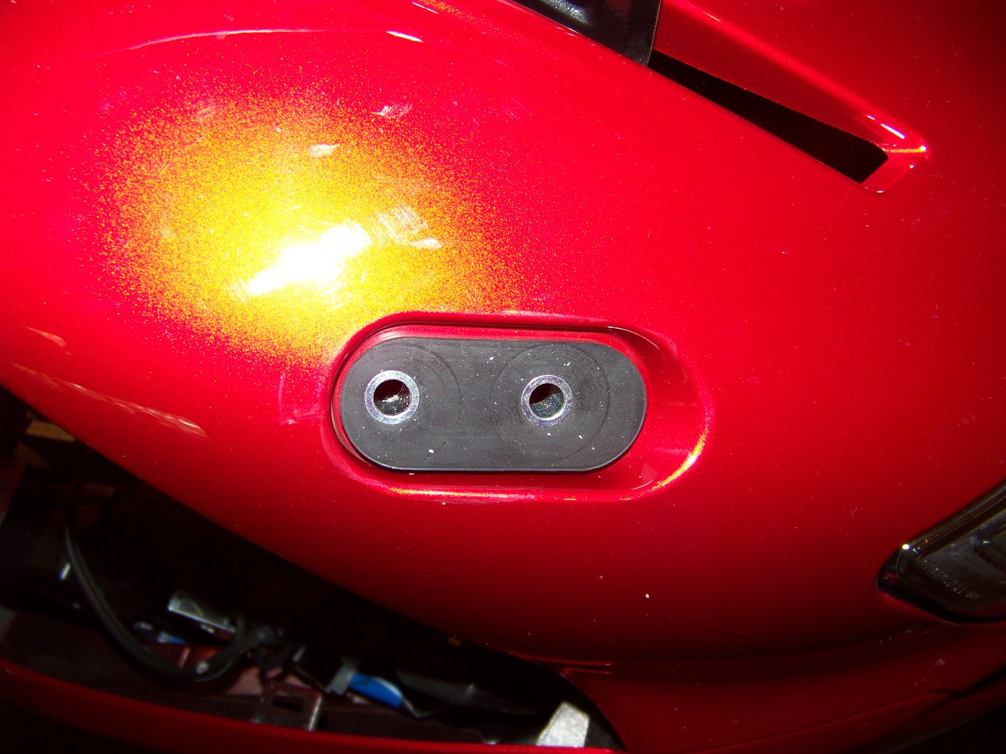
Once you have the rubber parts removed this is what's left. You can now see directly down to the mirror mount holes in the subframe, which will also need to be enlarged slightly to accommodate the FCCNs :
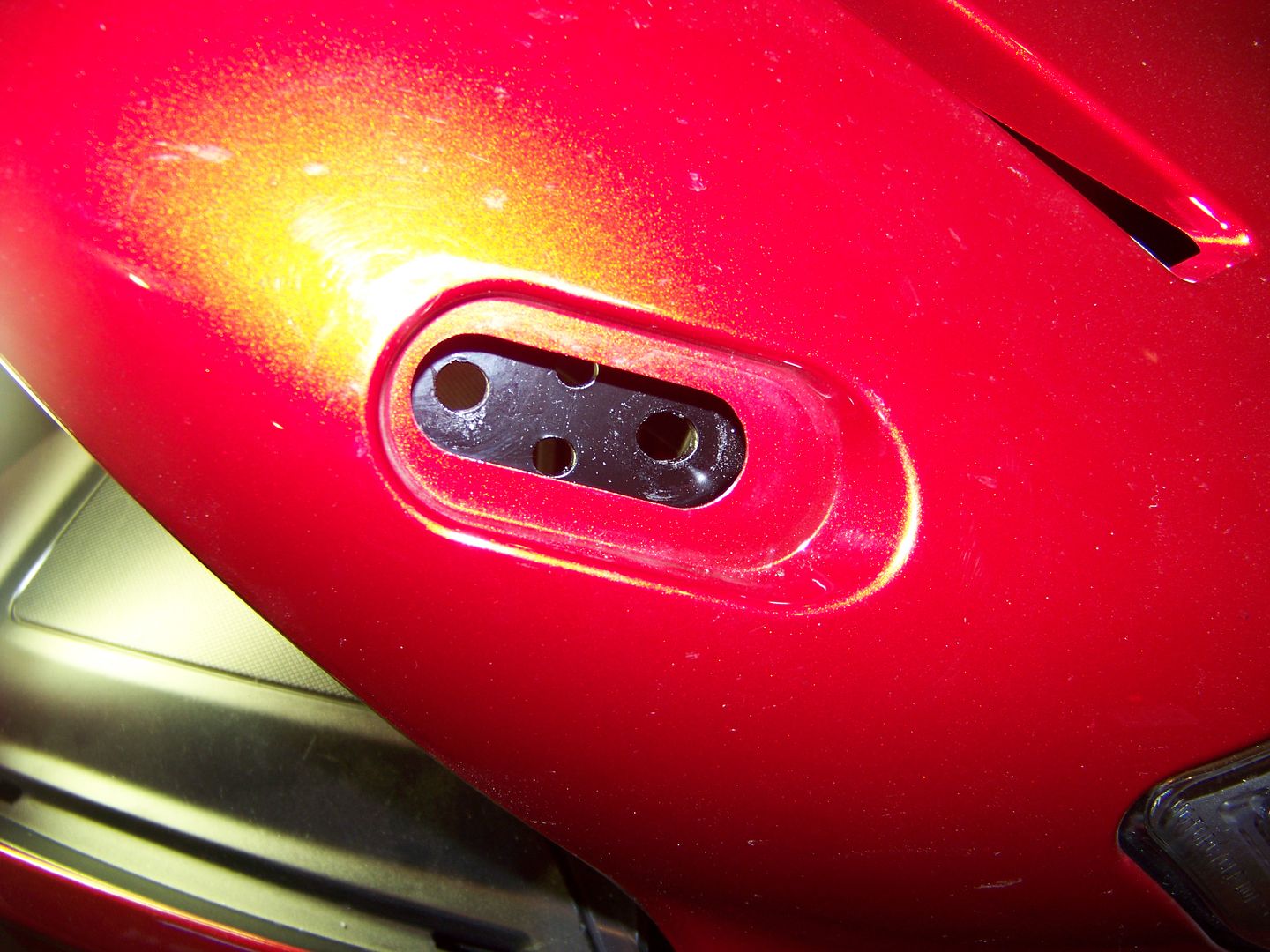
Photo above is prior to drilling. You can see that the holes are somewhat oval shaped. The casting is also kind of rough. Before disassembling I had made a note that the mirrors previously sat in the lowest part of the oval holes, so I would need center the hole enlargement toward that end.
The OD of the FCCNs are just under 8mm, so I used an 8.5mm drill bit. It became immediately obvious while drilling that the subframe is an aluminum casting, which explains the recent rash of broken subframes on 3rd gens. It is also pretty easy to drill out the mounting holes just using a hand held drill.
Once you have the holes enlarged, you'll want to replace the "Plate #1" between the subframe and tupperware, without the two collars installed, and then put Plate #2 back on top from the outside. Without the two collars there is nothing to hold Plate #2 in position, so we will probably want to attach it somehow (double sided tape) in the future.
By fiddling around with a combination of nuts and washers I found that we need ~ 10mm of spacer between the mirror mounting and the AntiVibe bracket. Essentially we will want to make up some 10mm thick aluminum spacers that are shaped identically to Plate #2. I'll be sending those dimensions (and maybe one of my Plate #2's) to Dave so that he can make up a set from aluminum, which will give us the largest possible surface contact area to the rubber mounting, and allow the greatest amount of stability for the entire mounted assembly.
Here are the pics of how it will look. The bracket will extend down along the front surface of the front faring, just like on the earlier FJR Generation versions. Obviously you would put your Aux Light's bracket mounting screw in the small hole at the bottom (countersunk on the back side).
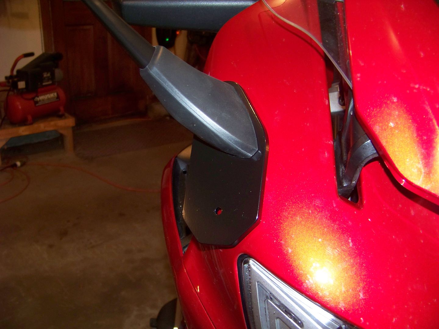
The bracket will be spaced a small amount away from the surface of the faring, which will eliminate any concerns over rubbing the painted faring surface underneath the bracket.
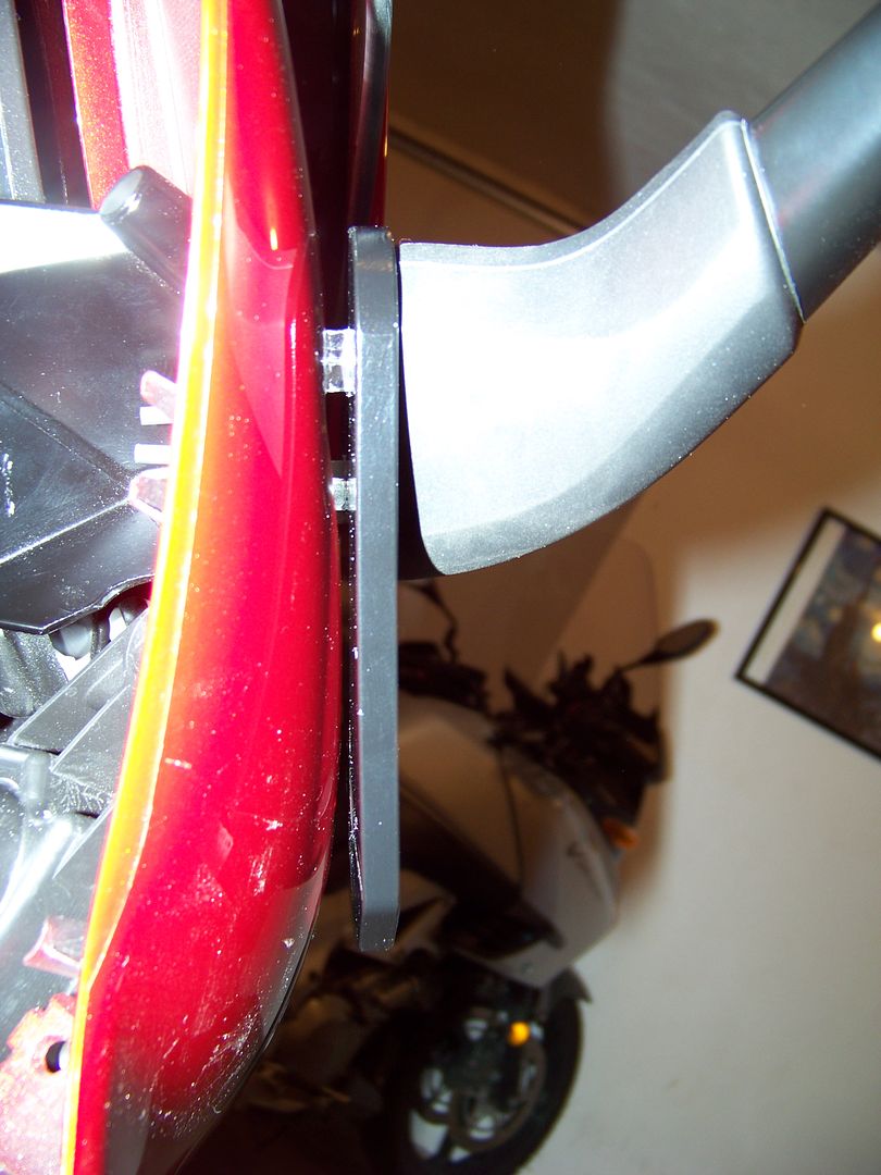
The photo above was taken with ~8mm of spacers installed. I want to increase the spacer thickness to 10mm, which will allow better clearance from the faring, and allow more room for the FCCNs to be used and be able to compress the rubber mounts without bottoming out internally, to provide full stability.
There you have it. Next step is to get some of the 10mm spacers made up, give them a beta test, and they should then be ready for distribution.
The questions yet to be answered are:
Will the assembly be "rigid" enough after having removed the two aluminum collars?
I suspect they will be because the holes in the Anti-Vibration Brackets are large enough that the collars were not really supporting the prior versions either. The contact of the AVBs with the front faring of earlier generations only supported the brackets in one direction. I think the mirror mounting itself will be adequate to support the brackets and a lightweight LED light housing.
Is this too much work, and too invasive of an installation procedure, for just some aux light mounts?
Consider that the FZ1 mirrors can be used right out of the box, without drilling the subframe. The drilling of the subframe is not an "irreversible" mod. You are only enlarging the holes to be about the same size as the widest part of the original oval. So, You can still go back to using the mirrors without the Anti-Vibration Brackets and the stock flange nuts, or go back to using the stock mirrors, if you wanted.
Theme by Danetsoft and Danang Probo Sayekti inspired by Maksimer