


[Pre-Edit 1 -- this procedure is valid for Gen I through Gen II FJRs. It differs only the using red Run/Stop/Start switch to reset any error codes, you toggle in Stop direction times seconds or less.]
[Pre-Edit II -- FU Photobucket. To view the photos you will need to install addons. Firefox fix Chrome fix ]
At the end of the test procedure I supply information on how to make a simple, permanent installation for the ABS test Coupler which makes this procedure easy to perform anytime. The following procedure is excerpted from a post I wrote in a different thread. This is the basic ABS and ABS Metering Block test procedure, pretty simple to do, just convoluted to read at first. As always, read and use your FSM for reference.
You can verify that the ABS system is working, actuate the spool valves in the ABS hydraulic Metering Block and move a tiny amount of brake fluid by using the ABS test coupler. This is good for the health of the hydraulic unit and will help prevent freezing spool valves. The ABS test coupler lives under dash Panel D. On the Gen I the test connector has its own little bracket mounted to the frame holding it down and it has a cap over it, on the Gen II the test connector is above the battery. Please refer to your FSM for all the details. The following is intended to give you an idea of what is involved in a basic ABS Pass/Fail test.
To oversimplify ABS activation method 1 to test the system:
- verify that the battery voltage is >12.8 volts or this test won't work; charge or replace as necessary
- put the bike on the center stand, in neutral
- with the ignition key off, remove the cap and jump the ABS Diagnostic connector's Sky Blue wire to the Black wire
- find a friend, offspring or wife to help, with the bike on the center stand ---->
- simultaneously hold both the front and rear brakes on
- turn on the key
- when the ABS warning light flashes there will be one pulse felt in the front brake lever and then two pulses at the rear brake pedal
- your helper will try to rotate the rear wheel; it should rotate for 0.1 seconds then stop, then rotate again 0.1 seconds on the second pulse
- turn the ignition switch off
- remove the jumper
Congratulations, your ABS system works.
Rotating the rear wheel when on the center stand may set Error Code 25 -- this is not an error or fault, disregard this error message. Because the front wheel was not moving while the rear wheel was turned by hand the ABS ECU thinks that the vehicle is moving but there were no pulses coming from the front wheel. The diagnostics for Code 25 specifically mentions that this will happen if the motorcycle is on the center stand and the rear wheel is rotated.
To oversimplify ABS activation method 2 to test the hydraulic system:
- verify that the battery voltage is >12.8 volts or this test won't work; charge or replace as necessary
- put the bike on the center stand, in neutral
- with the ignition key off, jump the ABS Diagnostic connector's Sky Blue wire to the Black wire
- turn the red Run/Stop switch to OFF
- turn the ignition key on and wait for 2 seconds
- now press and hold the Starter button for >4 seconds, the engine will not start; release the Starter button
- simultaneously operate both the front and rear brakes
- 0.5 seconds later the front brake lever will pulse twice; then the rear brake pedal will pulse twice; after the brake pedal stops pulsing, 0.5 seconds later the bake lever will again start pulsating and continue for ~2 seconds.
- turn the ignition switch off
- remove the jumper
- set the Run/Stop switch back to Run
Congratulations, your ABS hydraulic system works.
Deleting The Malfunction Codes
- Connect the Test Coupler or activate the Test Switch you installed.
- Turn the key ON. Any recorded malfunction Codes will be displayed.
- Set the red Engine Run/Stop switch to OFF. Be SURE the Engine Stop Switch is OFF or Bad Things can happen.
- Push the Starter Button at least 10 times in 4 seconds to delete the Malfunction Code(s).
- Turn the key OFF. Done.
By permanently installing the ABS Test Coupler and a test switch you won't have to jump wires or remove the Test Coupler. To test the ABS flip the switch ON (shorting the two switch contacts). Run the tests. Flip the test switch OFF (no connection between the switch contacts). Done.
Edit on 2/28/2014 -- It is my understanding that ~ 1 year ago Yamaha stopped selling this test jumper to the public. You can still use an alligator clip lead or any other wire to jump the ABS connector pins and it will work just fine and save you a few bucks.
This is what the Yamaha ABS Test Coupler P/N 90890-03149 looks like: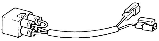
You can find the Test Coupler in many places, one place is Boats-dot-Net The part is <$10 but unfortunately the shipping is $10. For this procedure we are only interested in the jumper. The two connectors are intended only for volt meter connections. By putting a volt meter on these two connectors you can run the full battery of ABS tests, run diagnostics and read & clear ABS fault codes.
Modify the coupler by cutting the jumper: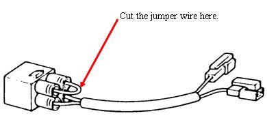
Now, add extension wires to the ends of the cut jumper. The wires carry almost no current so wire gauge isn't important, they just need to be heat and vibration resistant enough to hold up to motorcycle use. The wires need to be long enough to reach what-ever location you choose to mount the test switch.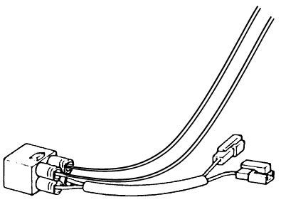
Here are a couple of ideas for a test switch. The first switch is one tough marine duty brass switch which is available with a rubber boot making it water proof. While overkill, it is also bullet-proof.
clickable pic
Radio Shack switch:
clickable pic
There are lots of sources for Toggle Switch Rubber Boots, such as Bass Shop Pro, AmpHexSeal, Parts Express and Allied Electric.
Mount or zip-tie the switch to the location of your choice. If you are going to panel mount the switch, consider putting a connector on the two wires to make it easy to remove the panel.