- Home
- Forums
- Ride Reports
- MotoBikes
- Restorations
- Wrenching
- 1963 BMW R69s
- 1969 BMW R60/2
- 1978 Yamaha 125
- 1979 KZ1300
- 1979 Kz1300 - Bob's Beauty
- 1981 CBX SuperSport
- 1981 Kz1300 Model A3 - Chocolatie
- 1984 Ford F250 XL
- 1987 ATK
- 1987 MowieMowie
- 1987 RotoTiller
- 1988 Honda Accord Lxi
- 1990 BMW RT100 - Barrie
- 1991 Harley Davidson FLHTCU
- 1992 Johnnie Deere
- 2000 YZ426
- 2002 Dodge Ram
- 2006 Carson RacerX Trailer
- 2006 Host Camper
- 2006 KrZy8
- 2007 Wabs
- 2012 KTM 690R
- 2013 Naomi - FJR 1300
- 2014-08-01 Air Compressor - Sears
- 2017 Kioti
- 2018 Toy Hauler
- 2020 Honda Fit
- 2021 Miscellaneous
- 2024 Log Splitter
- 2024 NeoDyne MC Lift
- 2050 test
- Lil Trlr
- Eats
- RIP
- PC Not
- Cages
- Test
- FJRF Best
- For Sale
Candy Butt Association
World's Wimpiest Riders
You are here
2018-10-08 Saving KrZy8 (230k Service)

Forums:
2018-10-08 Saving KrZy8
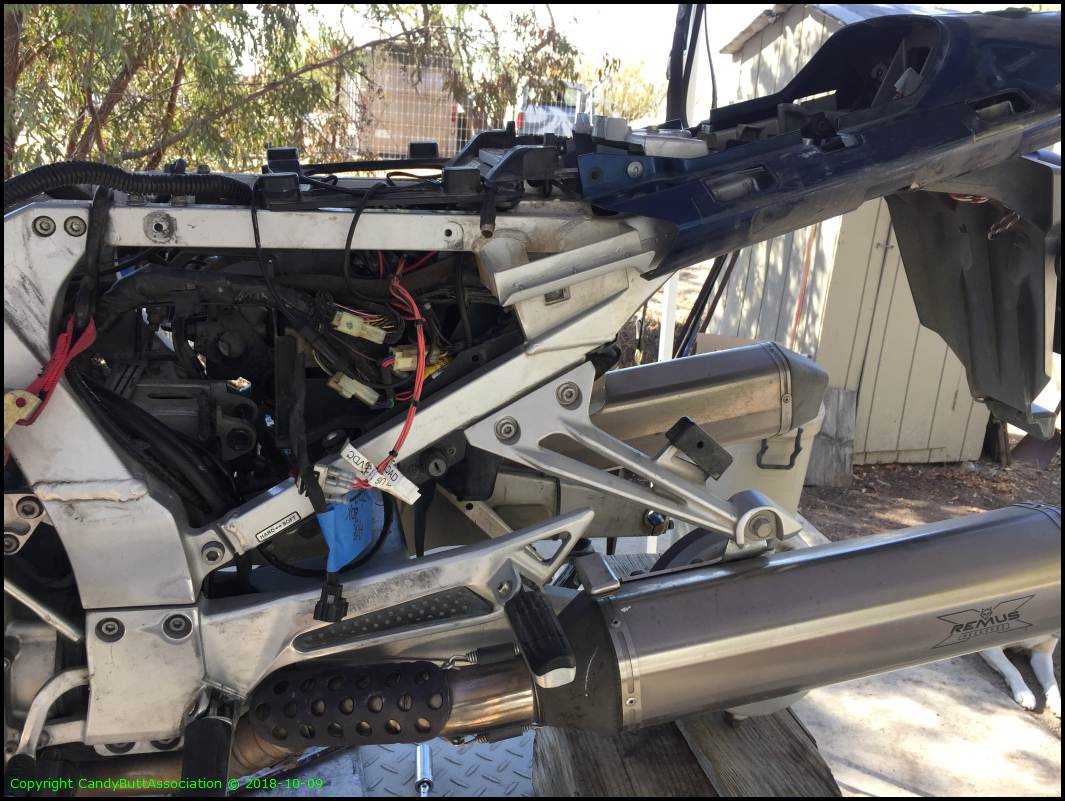
With nearly 250,000 miles, and with Naomi, a young blooded 2013 assuming the Long Distance Ride mantle, time to show KrZy8 some love. Off the top is:
- New starter motor - rebuilt one is kind of slow cranking so am trying brand new factory fresh as it's a PITA to access the starter..
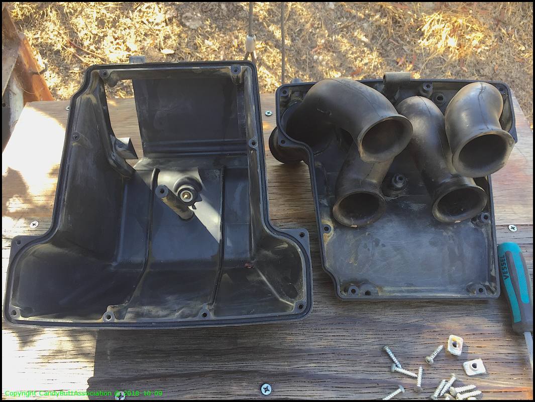
- New to me airbox - OEM circa 2006 had shrinkage on the runner 'boots' that connect to the throttle body making #2 cylinder hard to connect
- Clean up Brodie's ignition relay harness - wire shrinkage due to heat cycles resulting in exposed hot and ground exposed wires at connector entrance
- Throttle body cleanup - why not, there off and now's the time
- Fresh fluids - radiator, oil, final drive
- Freshen suspension - ship to GPS, right front fork seal leaky
- Remove StarComm/Zumo 550 wiring and enter the bold new bluetooh era
- New throttle cables - frayed at grip
- Valve clearance check
Photos to document wiring, routing, bolting, etc configuration. It will be some time before KrZy8 is re-assembled.
Bolts with large shoulders loctated to rear of 6 identical bolts holding front seat bracket.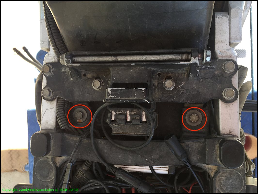
Aux relay ground point.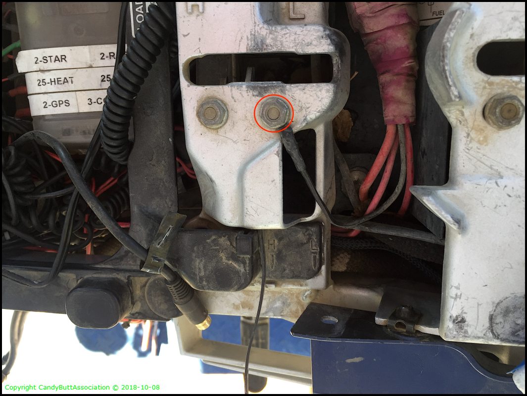
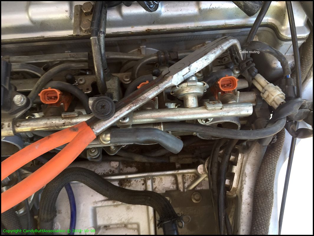
Cruise control cable routing.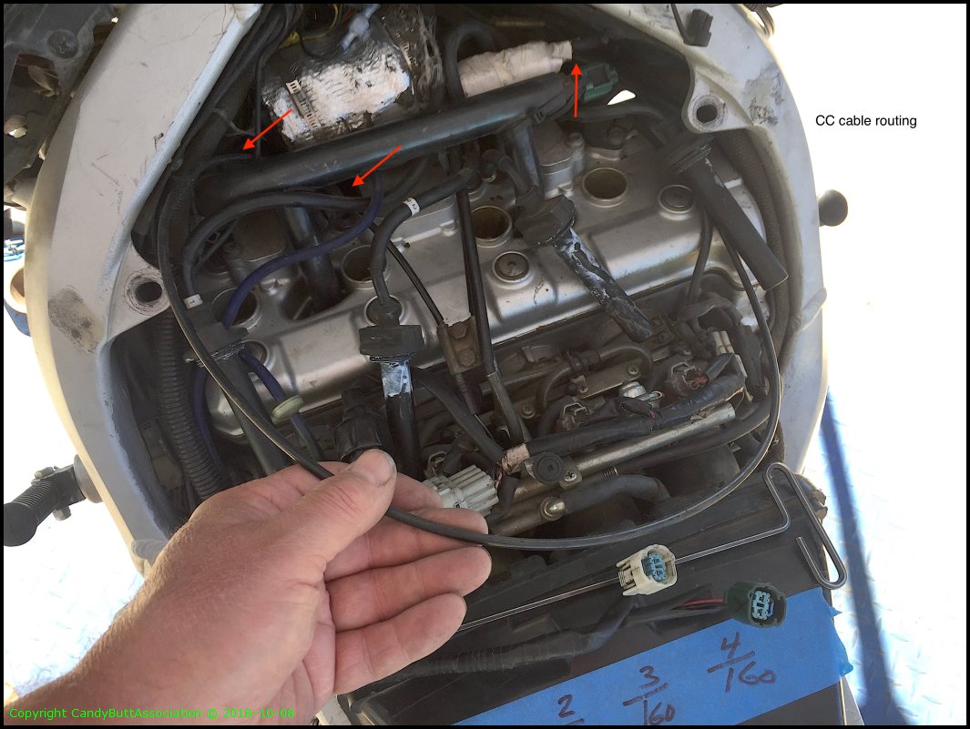
CC cable bracket.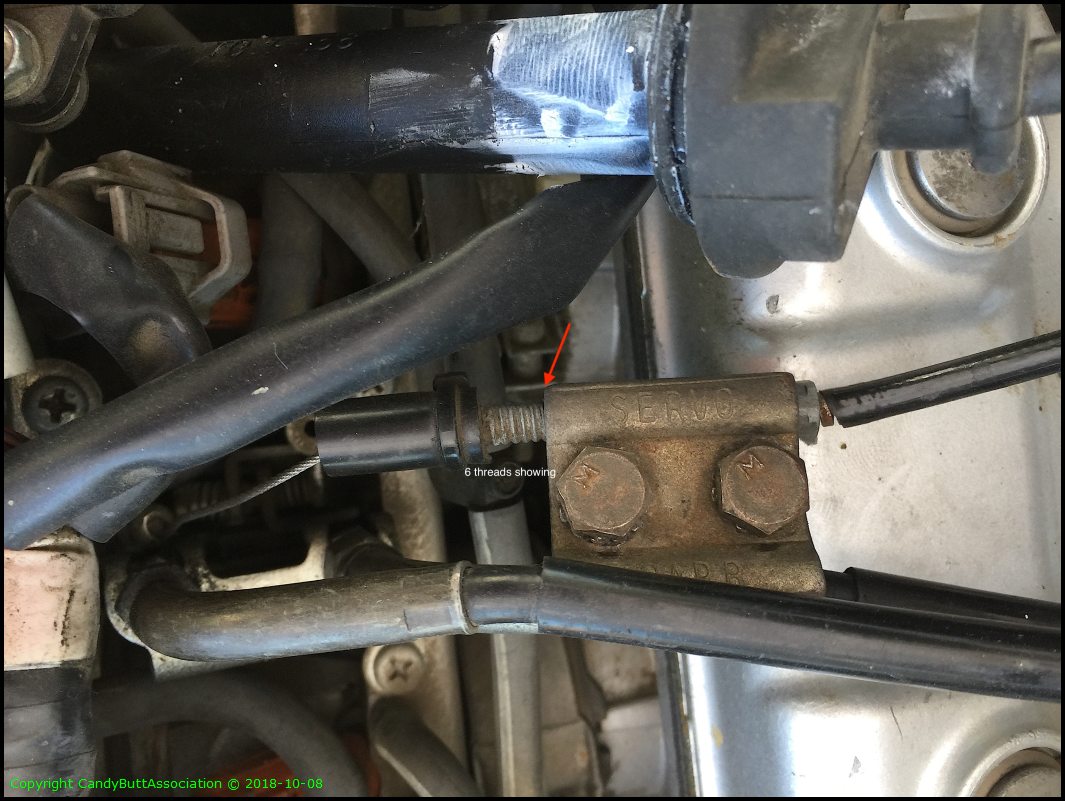
Spark plug wire routing under water pipe.
Airbox to TB clamp orientation.
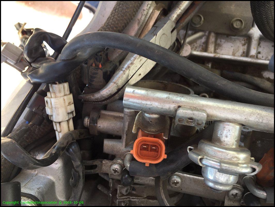
Injector 1.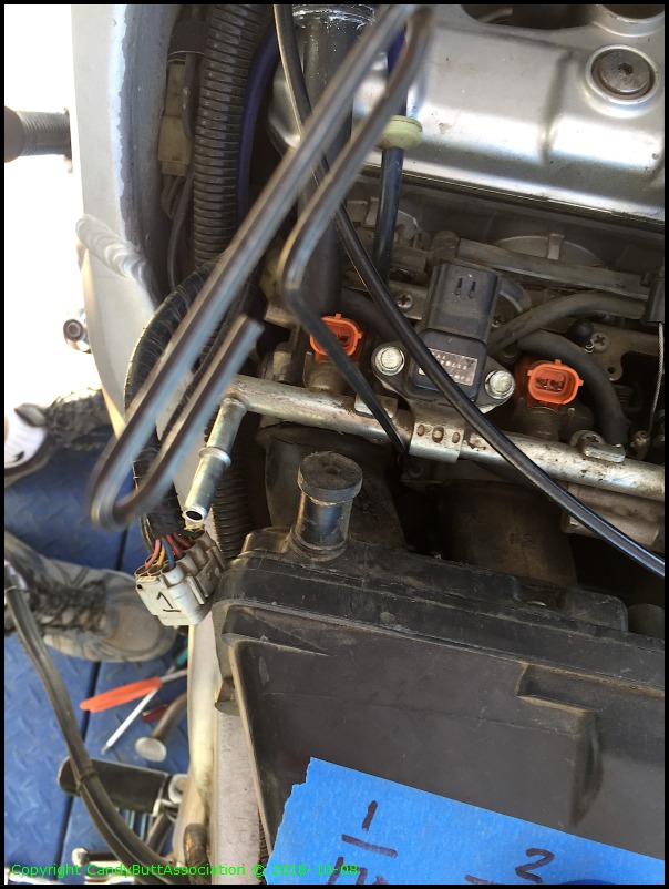
Injector 2.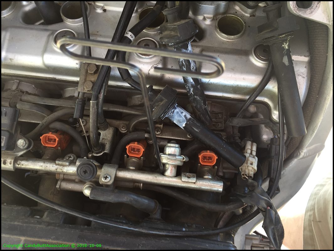
Injector 4.
CC cable attachment to thorttle body.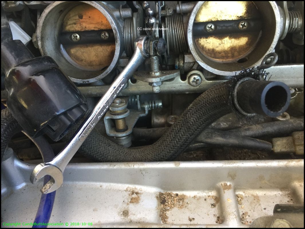
Cable clamp, RHS top of TB's.
.
Removing water pipe.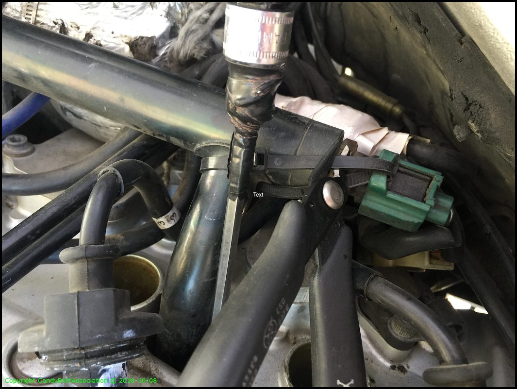
Don't forget the small water hose off LHS of main water pipe. Kind of hard to access.
Another view.
Removing CC module.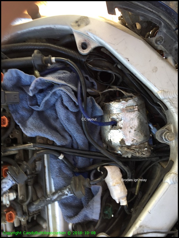
Wiring clean-up needed. It's been in service since 2006. Installed at Barabus house by Smitty!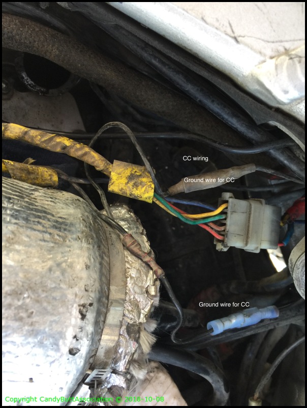
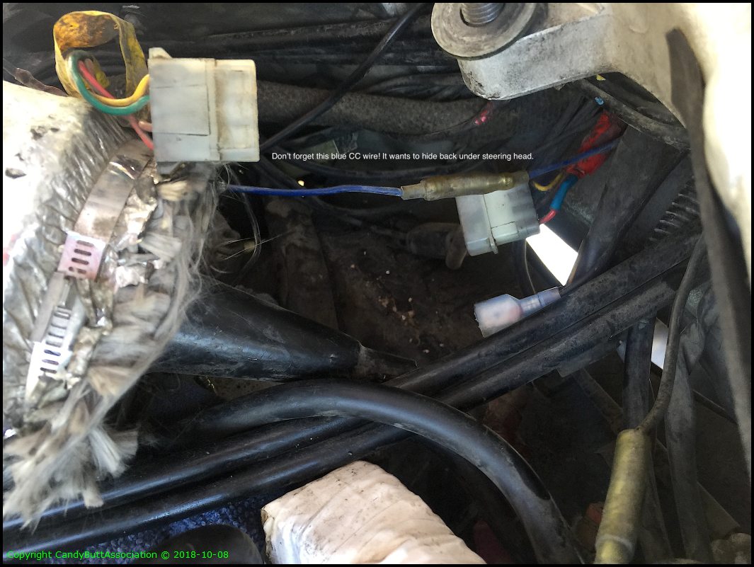
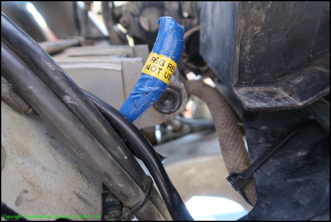
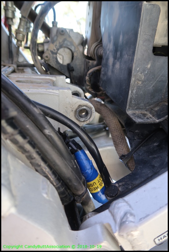
This blue wire.. don't forget it! and the RHS will hide under the triple tree.. so remember it's there, Don!
These two water hoses will be difficult to install. May have to get another set of hands to assist.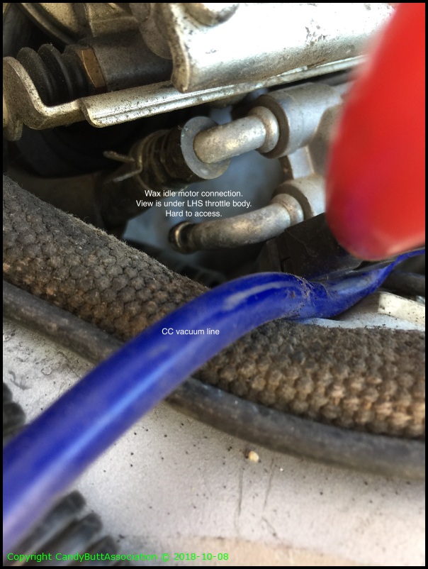
Here's why.. it's under the LHS of the TB.
New throttle cables are being installed so the old ones need come off. Cables frayed at grip.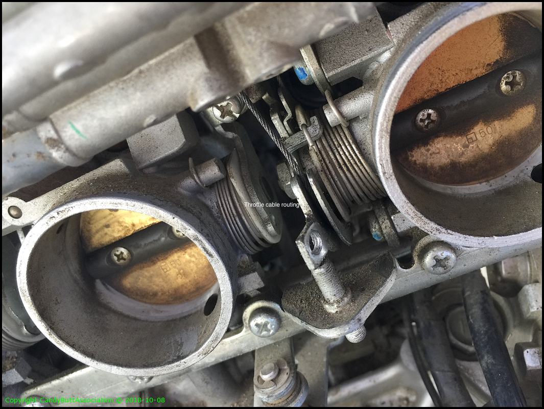
.
The front side cable can be removed by lossening the cable adjusters.
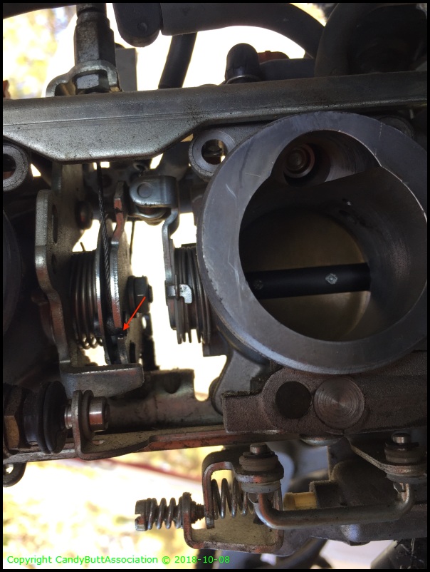
The pull cable, TB backside, requires the butterfly's be held open to allow adequate slack for removal.
Starter motor removal. When out, be sure to not blow debri into the engine internals. This motor was leaking slightly past the seal.
New motor installed.
Almost done for day 1. It's alot of work. Glad I'm not paying a dealer shop rate....
I removed the wings to allow closer access to the bike. What a back saver! Next lift I buy will need to have more easily removed wings.. This one is kind of a PITA.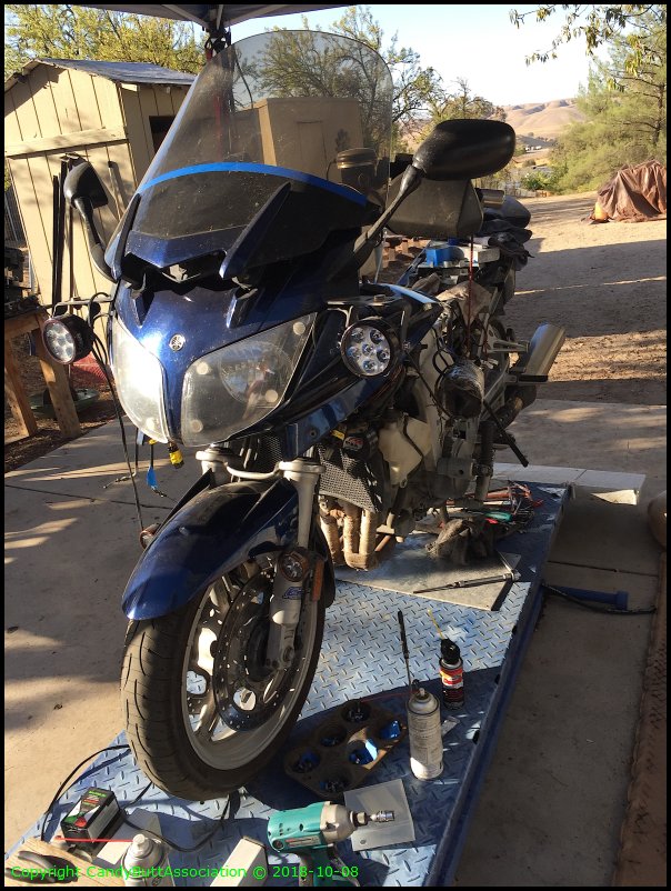
Last shot..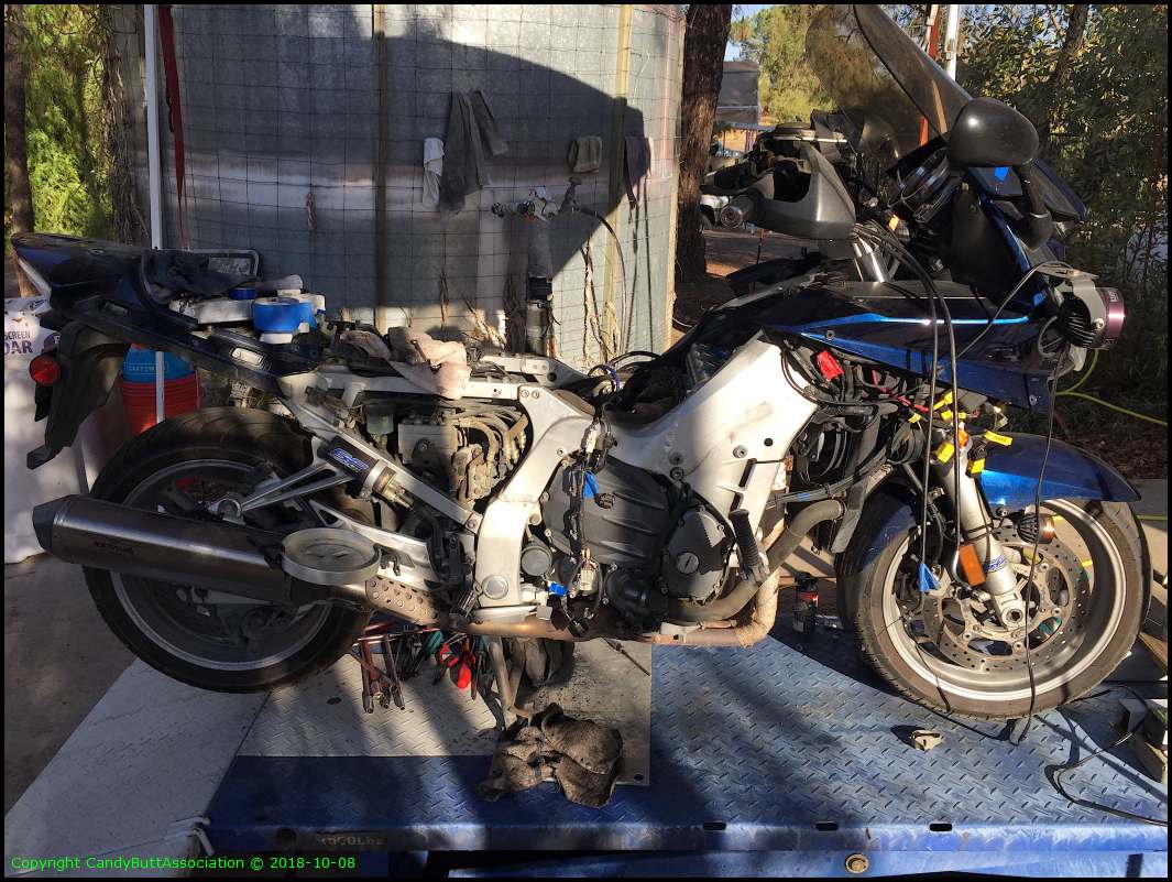
More to come..
Theme by Danetsoft and Danang Probo Sayekti inspired by Maksimer
2018-10-09 Shock and Fork Removal
2018-10-09 Fork and Shock Removal
Time to refurbish front forks, RHS has leaky seal and rear shock. Off to GP Suspension in Oxnard, CA.
.
The ashpalt loom protects a heavyt gage direct charging wire from RR to battery.
.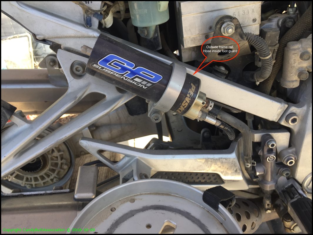
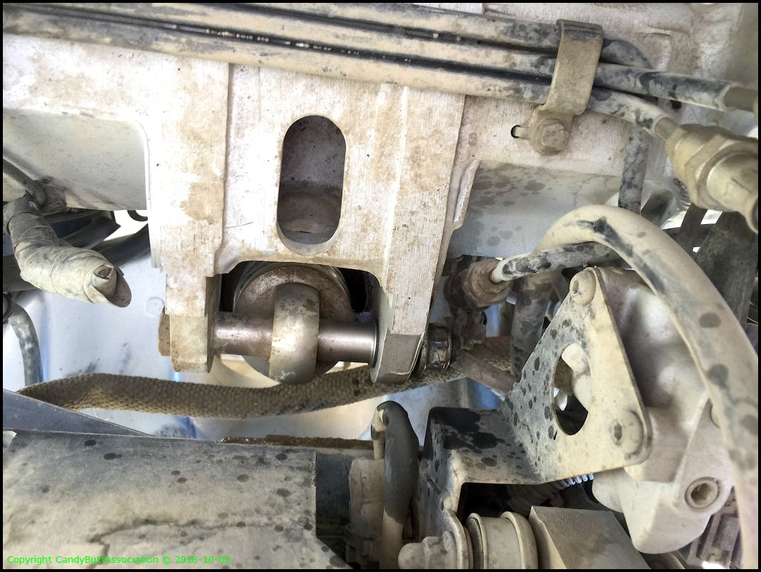
Resevoir hose routing.

Another view.

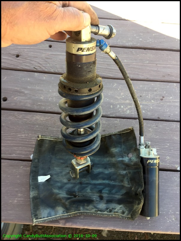
Extracted! GP S reminded me last time to periodically remove the boot and blow out any trapped dirt road DG granules.

Not too bad..
Packaged and ready for UPS.

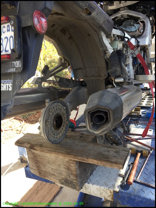
Getting more naked every day!
.
Radiator in good shape.

2006 OEEM air box innards. Could not find any good reason why runner #2 is almost 1/8" shorter than the other runners.
More to come..
2018-10-15 Well Crap
Attempted valve check today. Arggh.
Removed RHS crankcase coverer
Mistake 1 - Smart people remove the access cover, set everything up for cyl 1 top dead center
Mistake 2 - Remove cover, even when 'tight'. The freaking pin holding the CCT came out with cover, the CCT drifted down and can't be re-located unless CCT is relaxed.
2018-10-15 Valve Train Clearance Check
edit
2018-10-15 Valve Check Blues
With intrepid visions of success, started by removing the crankcase cover.
What the hell? Why so hard to remove? Tap tap tap tap with soft hammer. Wiggle Wiggle Wiggle top bottom sides.
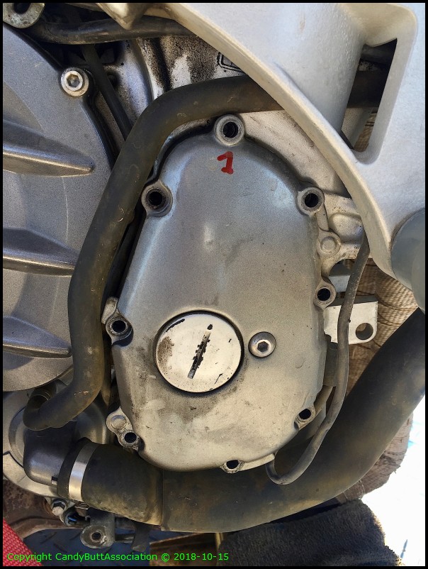
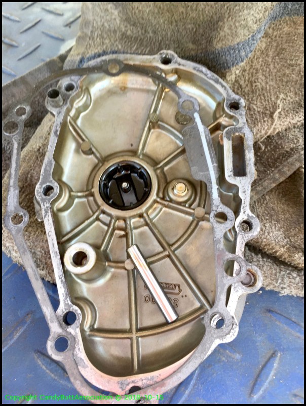
Ahh, Nucking Futs. The pivot pin which holds the CCT in place came out too. And of course, the CCT won't allower the slipper or shoe to move upwards so at some time the CCT must be slacked or removed. Which OK as the gasket is leaking any how and needs be replaced.
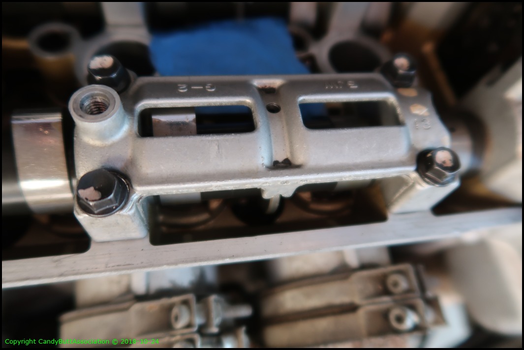
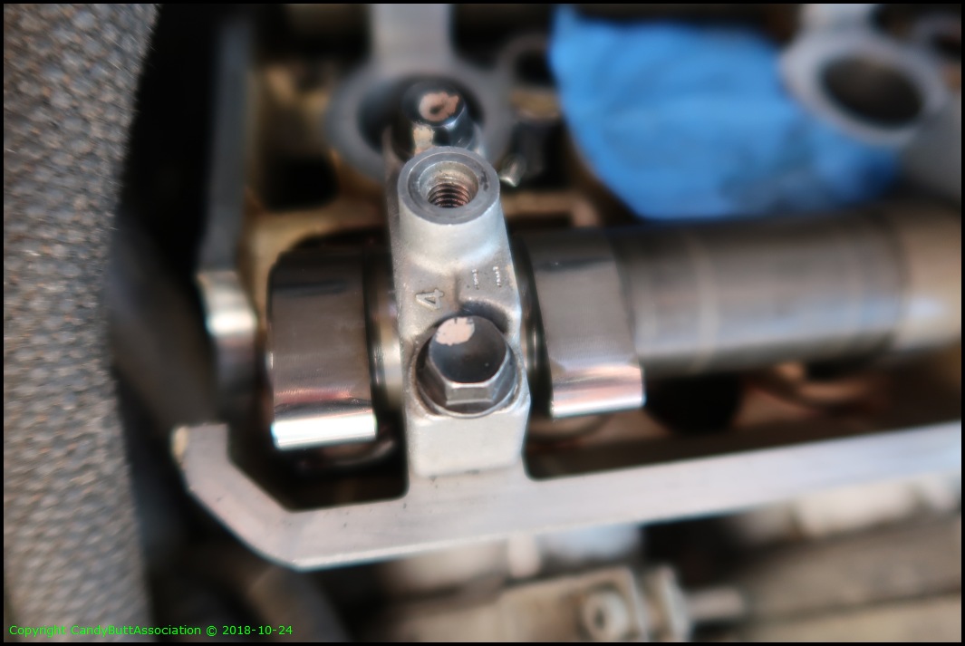
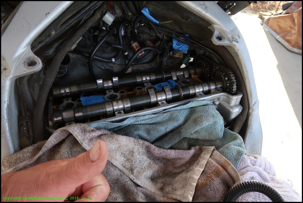
Well, Nucking Futs times2! Found this part on the lift after removing the valve cover. Where does it go? It looks like part of a CCT slipper. But where? It's not torn, or broken, and has only light rub marks so it's not in constant contact like the intake side slipper. At least that's my theory. Looked for about 5 minutes said screw it and continued on. Sometimes the answer is found somewhere else in the journey. But it's bugging me bad.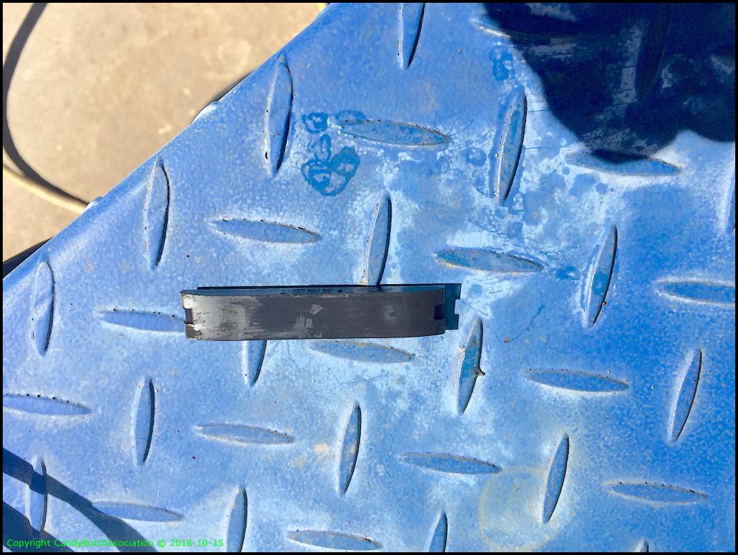
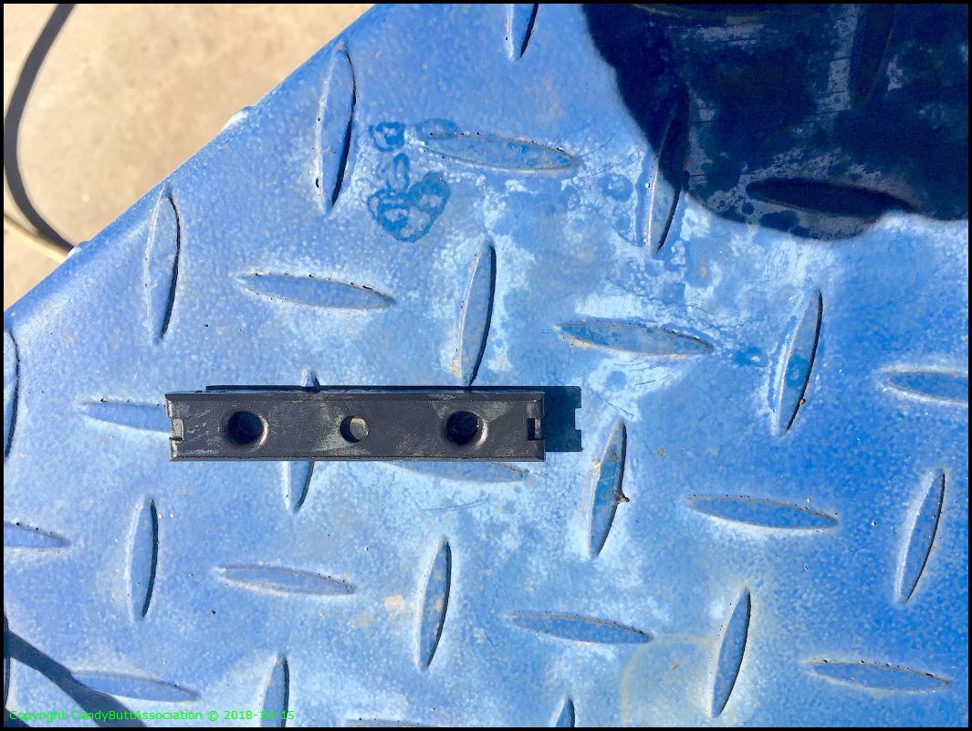
The other side.
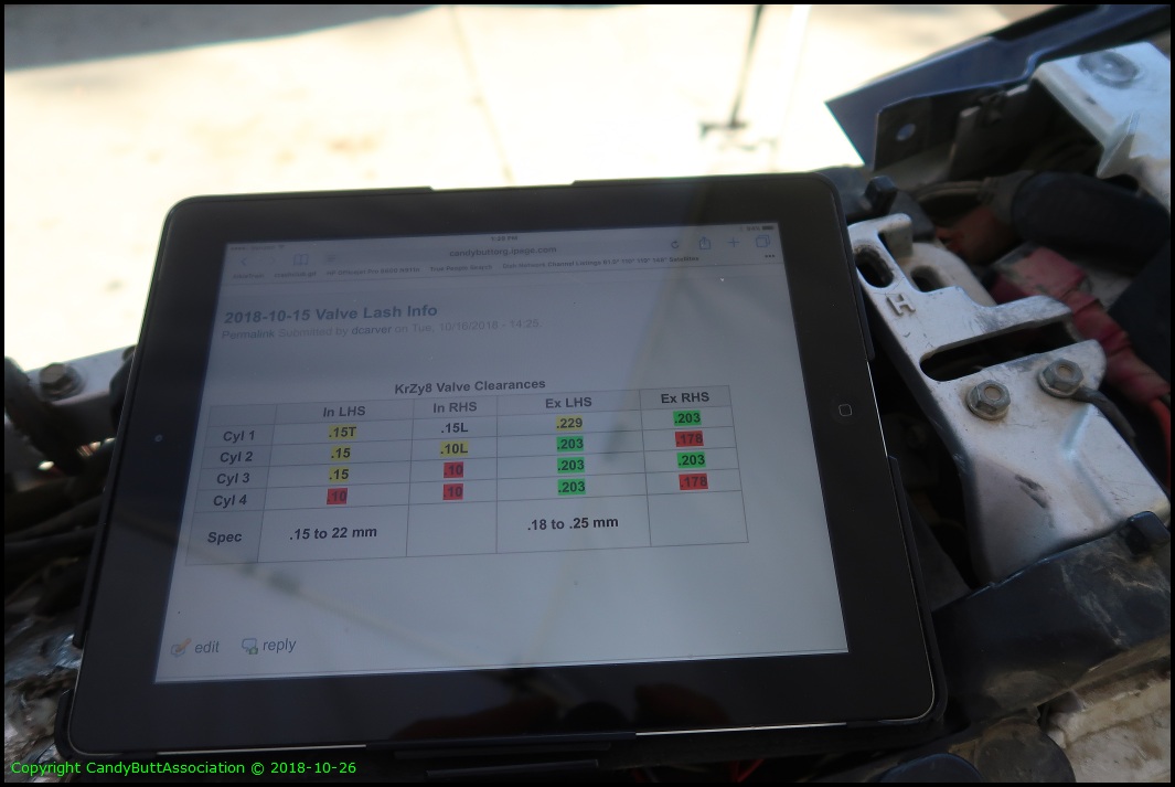
The specs for valve lash.

OK, this MIA part thing is driving me KrZy8. Poking and peeking at various locations.

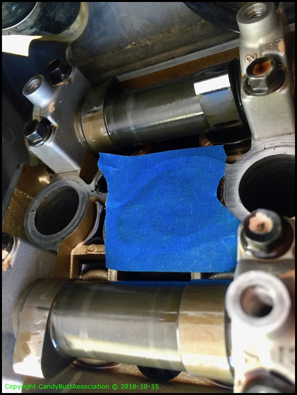
Got smart, Tx for the tip FjrFourm peeps, to cover the water inlet holes. In the nuclear world we called this Foreign Material Exclusion Area.
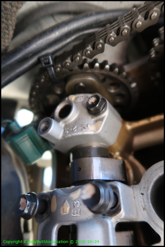
No joy, so continue on with lash checks. Two holes TDC on #4.

Lobes opposite each other.

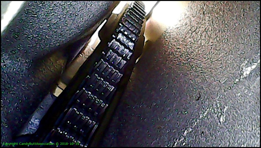
Damn It! Where DOES that MIA part go? Broke out the bluetooth endoscope. Here's the CCT guts.
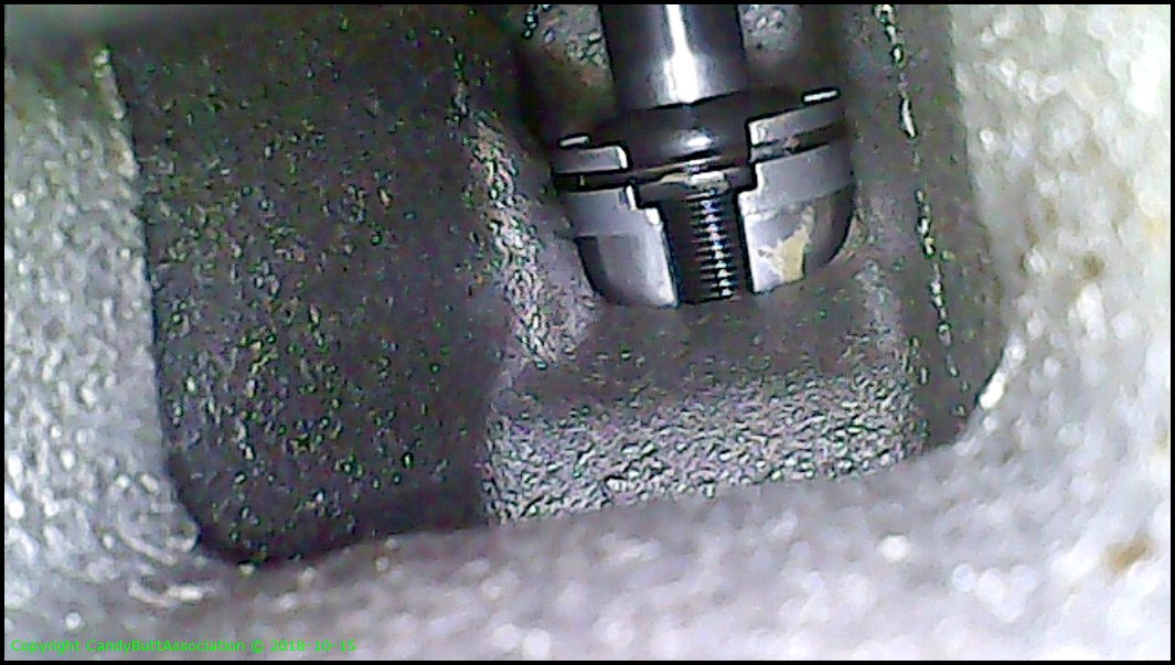
Cam chain tunnel. Doesn't look like MIA part came from here.
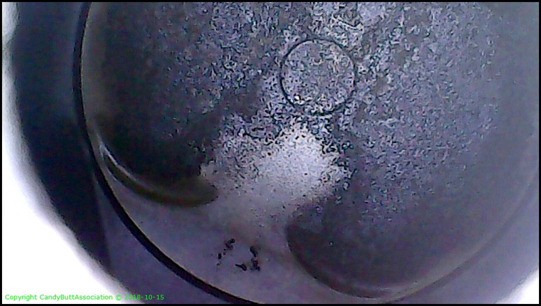
The endoscope is kinda coolio! Here's a piston crown.
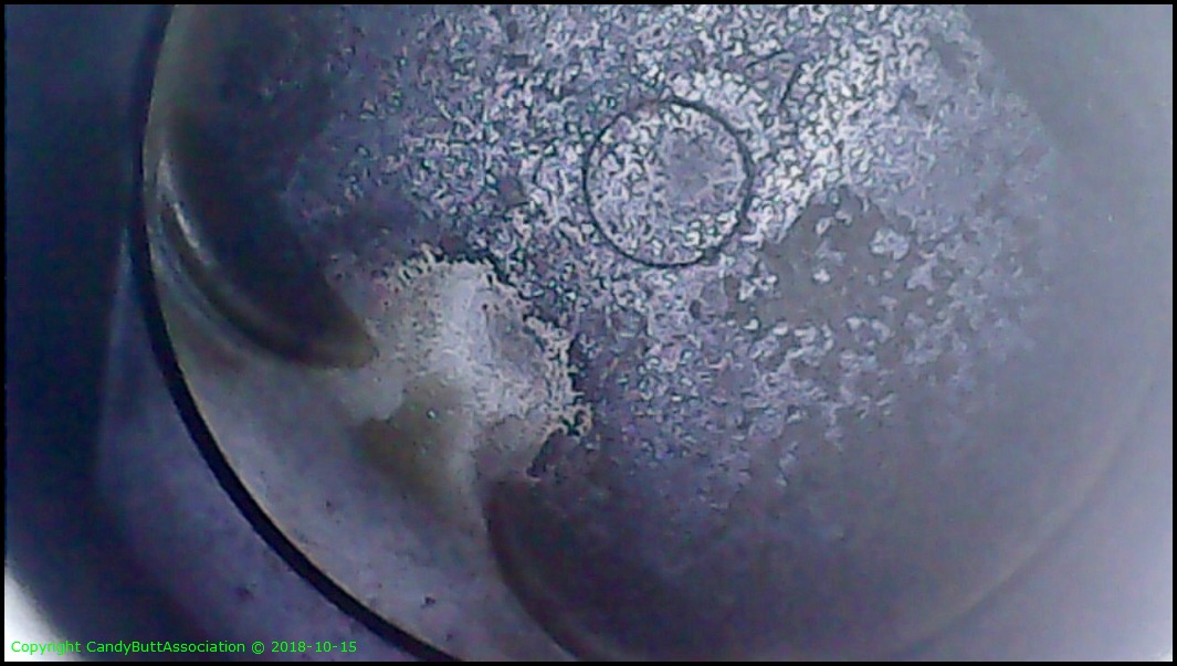
And another one. It pays to use top-tier fuel with a dose of SeaFoam every 5 or so tanks.
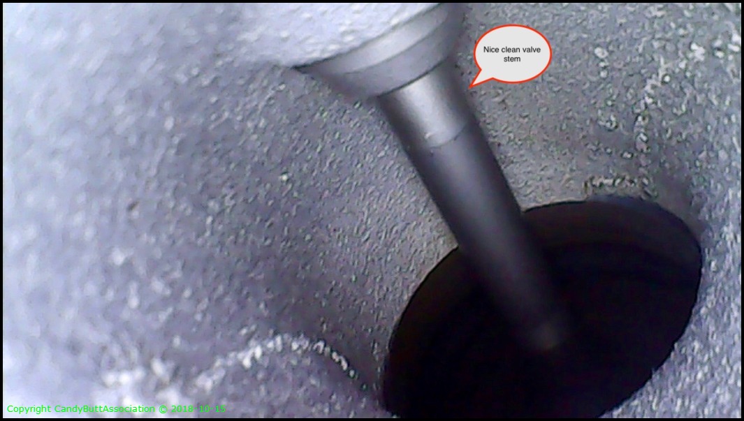
Valves look pretty too!
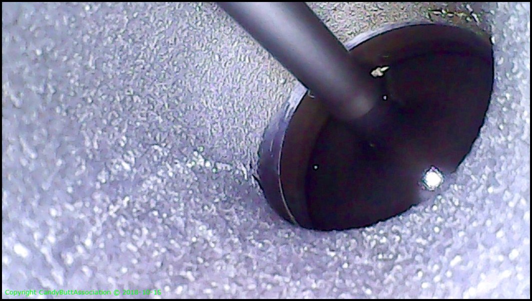
Hey Baby, wanna see my valve stem?
Aha! Found where the PITA MIA part belongs! Joy be to the world! All is good in the dCarver world again!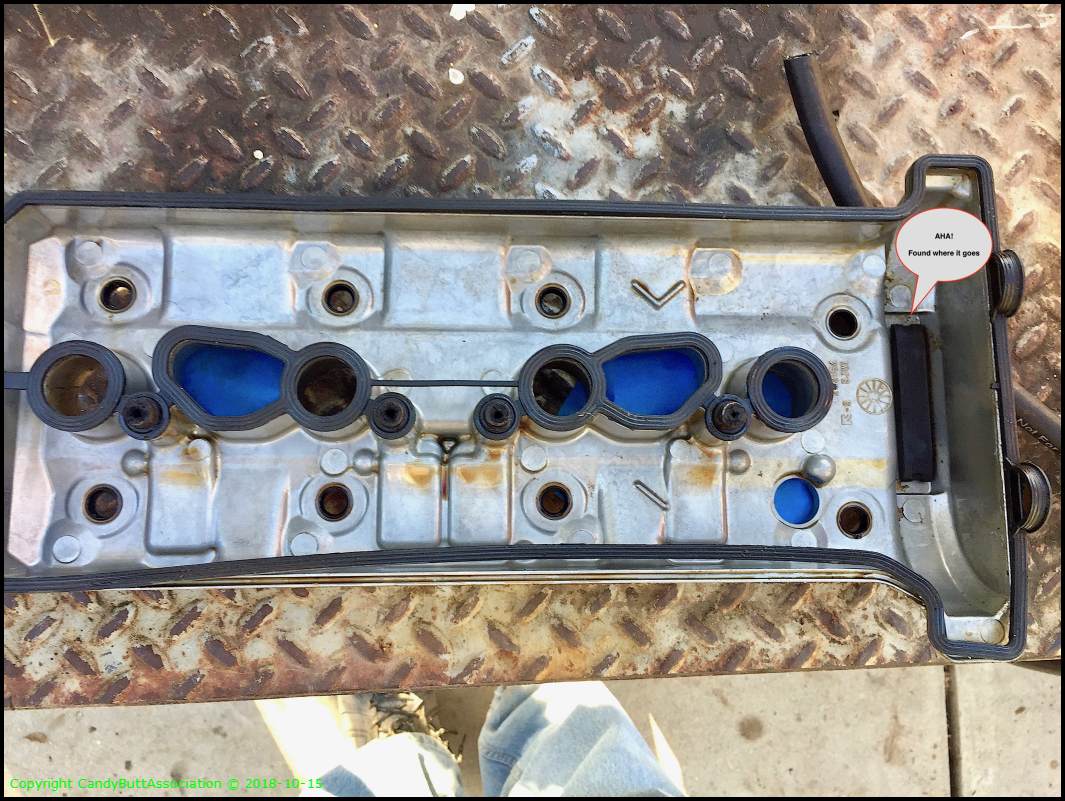
Sooo then, looks like I'll be lifting cams to make adjustments. Yamafitter used to have a most coolio Xcel spreadsheet. I need to find it.
And I'll deal with the CCT pin later.
Some questions, if I may ask for help?
2018-10-15 Valve Lash Info
.18 to .25 mm
.
2018-10-19 Suspension Install and Brake Woes
2018-10-19
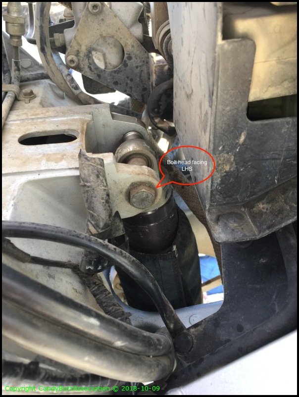
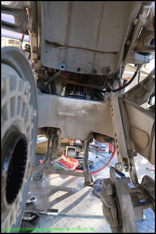
Forks and shock returned from GPS so time for some re-assembly.
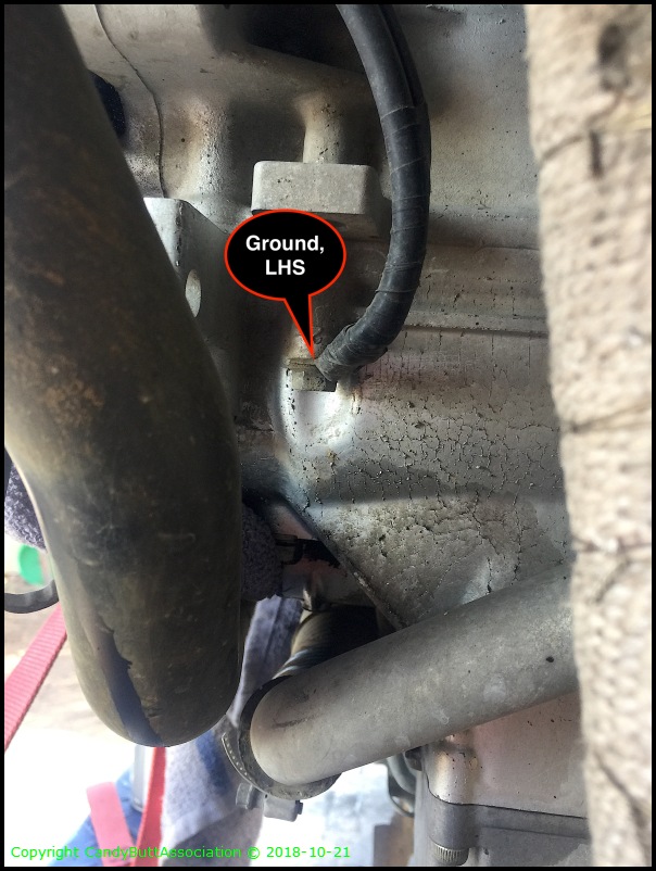
This connection OEM to main harness from RR. I bought a 'direct wire' kit to battery so this connection abandoned in place.
LHS.
Another view.

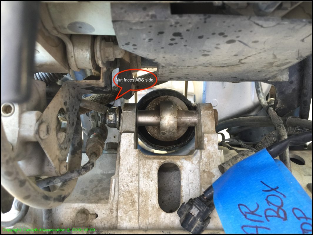
Shock installed. This time without dust cover. Alot of debri was caught in the sock and was rubbing on the shaft.
Prettty pretty.

As she sits.

Time for front fork install and new brake pads.

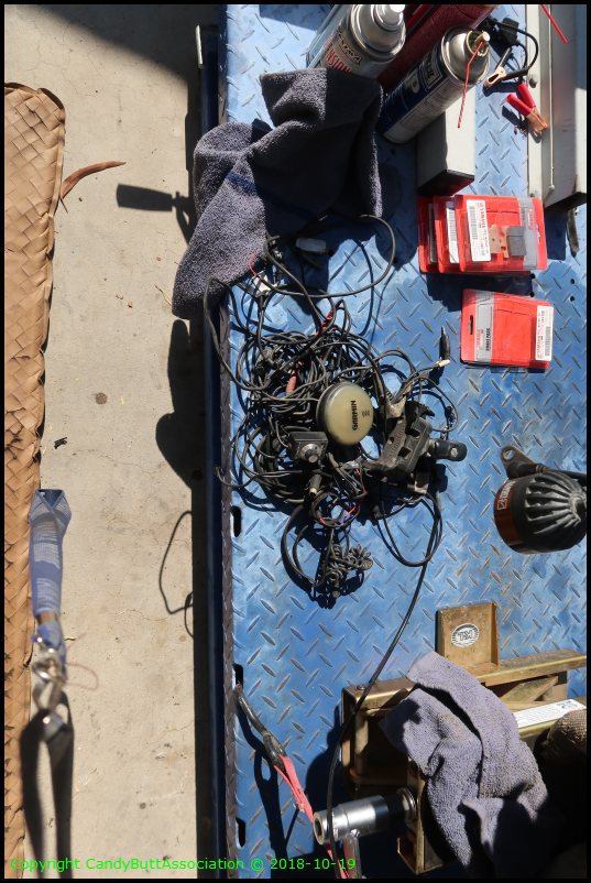
Removed a shit load of copper. I've gone BlueTooth baby, so Zumo 550/StarCom is gone.
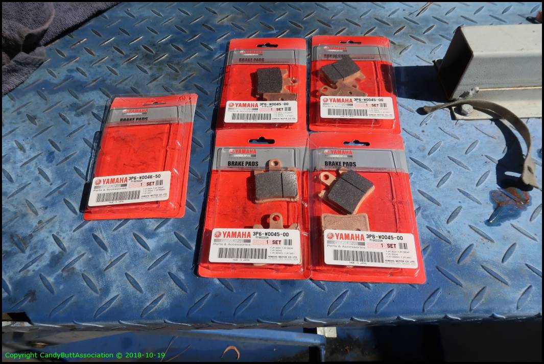
What's needed for front brake pad replacement.
So then. Heavy maintenance on KrZy8 with almost 250k.
Today was install front suspension and brake pads. EzPz. Been there done that.
But Noooo..
The LHS front brake caliper, the non-linked side, the pistons are 'auto' closing. They will not stay in the 'spread' position.
So I went to the RHS, the rear-front linked side, and all is good. The pistons stay 'spread' to allow caliper installation onto disk.
The LHS though? The pistons are closing sufficiently to hold two fairly large screwdrivers between the pads. And they pistons move pretty darn quickly too.. way too fast to install onto the rotor.
Never seen this one before, any ideas?
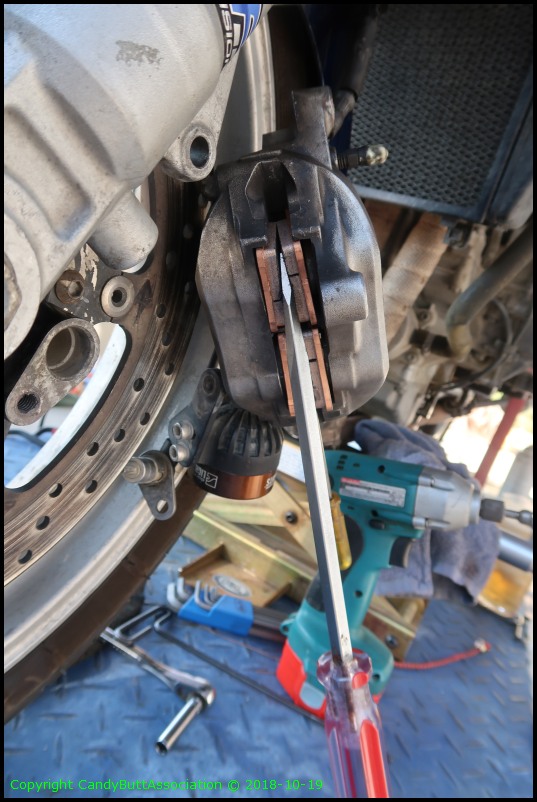
Note that the pads are 'auto' closing sufficently to hold the screw drivers in place.
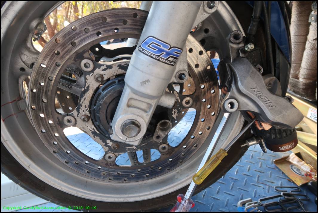
Most perplexing. Why the 'auto closing'?
FJR Forum responses
FJR Commander
Posted 19 October 2018 - 04:16 PM
Can you push the pads back and have them stay if you open the LHS bleeder?
Is the upper piston pair on the RHS behaving?
I wonder if you have a blockage in the hose to the left caliper?
Is the ABS working on the front - maybe something wrong with ABS pump but I think that would affect both sides?
#3 Redfish Hunter
Gone Fishing
Posted 19 October 2018 - 05:04 PM
My first guess would be a bad brake hose restricting flow back into the master cylinder. I have seen this before on trucks. How old are those brake hoses?
Never run out of ideas, real estate and traction simultaneously.
#4 gregory
Great things are afoot
Posted 19 October 2018 - 05:26 PM
Gunny for RFH
"You can't get a suit of armour and a rubber chicken just like that. You have to plan ahead."-Michael Palin
"When you set sail for Ithaca, wish for the road to be long, full of adventures, full of knowledge." C.P. Cavafy
#5 philter
FJR Pilot
Posted 19 October 2018 - 06:03 PM
The only thing my peabrain can figure is that the four pistons in the left caliper are loosey goosey and are being pushed back closed by the trapped air in your master cylinder, and the pistons in the right caliper are a little "sticky" and therefore aren't responding to the pressure.
2018-10-20 BrakeWoesFixed
With gratitude to FjrForum peeps and personal friends via email..
YEP! Problem solved. Wayh overfull master cylinder.
Records show I flushed the system about 4 months ago.
With skinny pads.
And I tend to put fluids at high level marks.
New 'fat' pads installed and, guess what? Fluid has to go somewhere.
When I lifted the MC cover.. brake fluid gushing out.
Mystery solved
Thanks again, Peeps!
2018-10-21 Throttle Cables Pivot Pts Sliders HiWay Pegs
edit
2018-10-21 Throttle Cables, Sliders, HiWay Pegs, Grounds
Still waiting receipt of HotCams shim kit so off to other work.
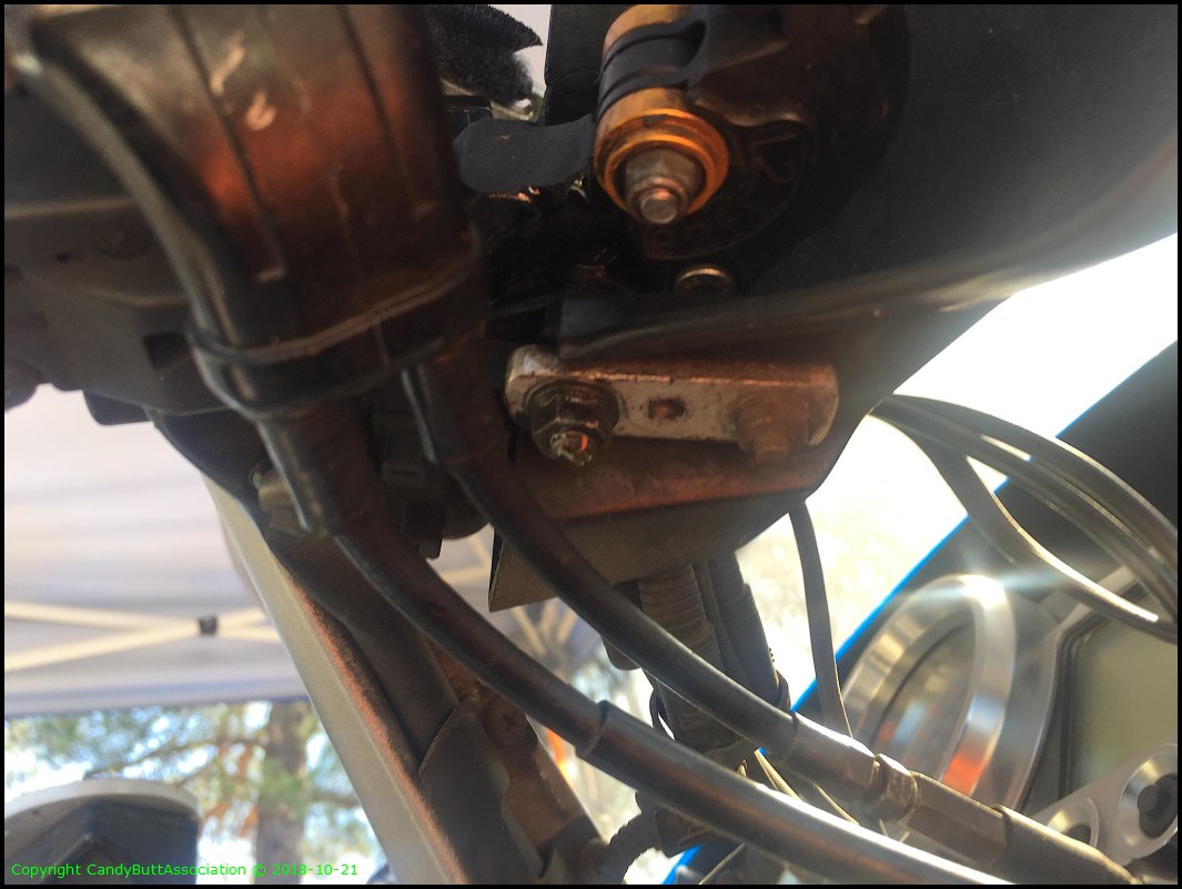
Clean ground.
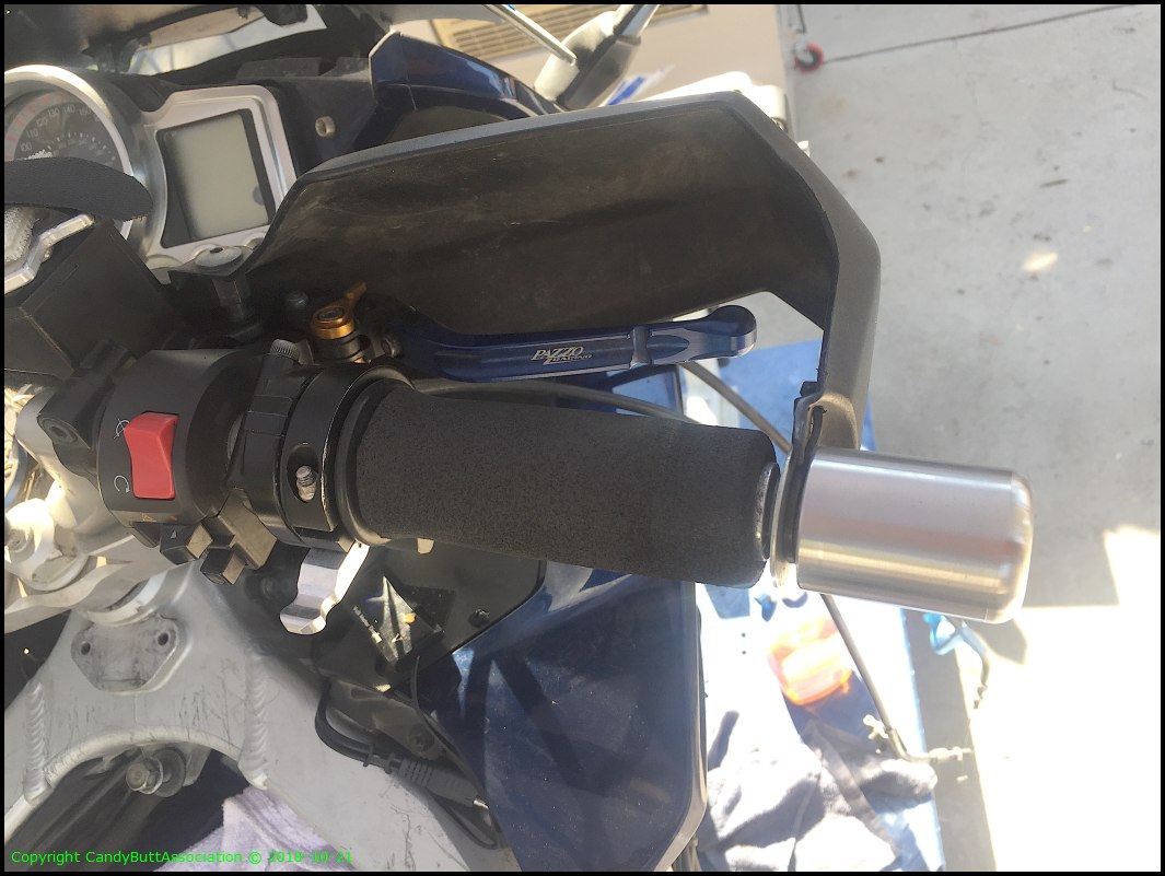
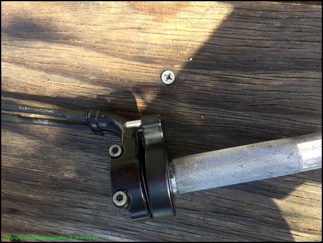
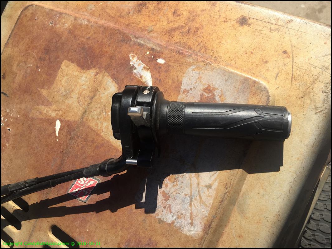
Replace throttle cables. The hardest part was removing the factory grip. A real PITA.
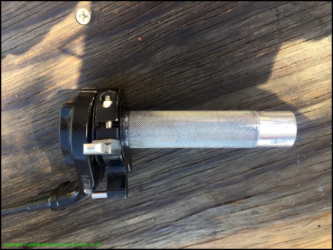
New cable part numbers.
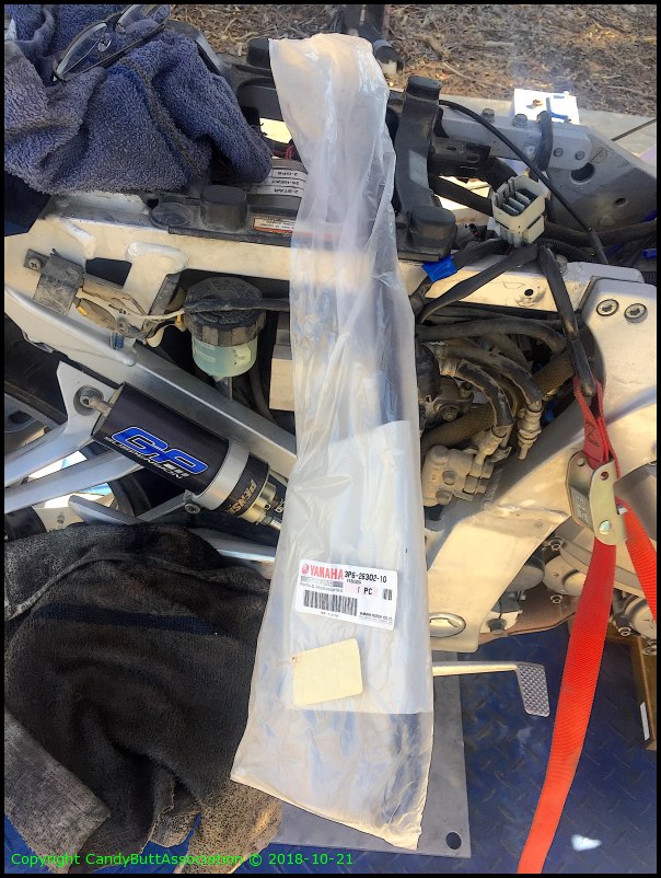
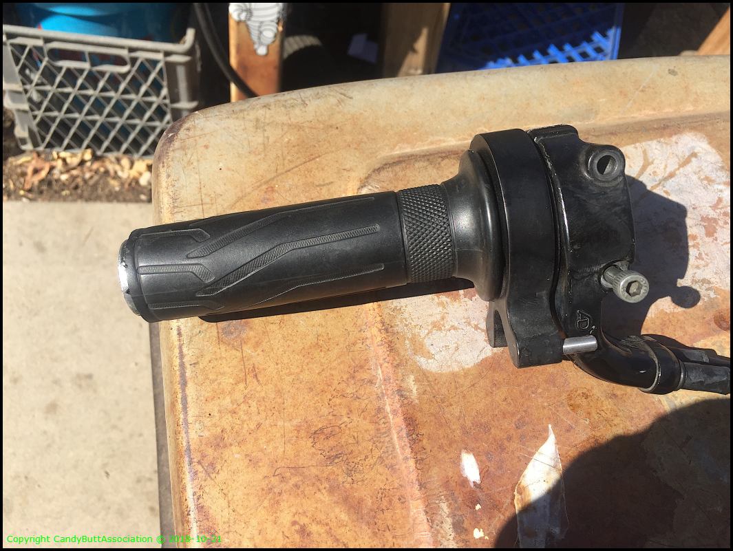
Last installation.
MadCo throttle lock orientation.

Different view.

.
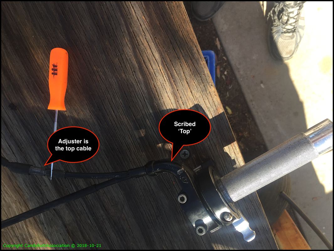
Marked the cables prior to removal.
Brake hand guard configuration.
Garuld needs to start making these most coolio hiway peg/slider combo.
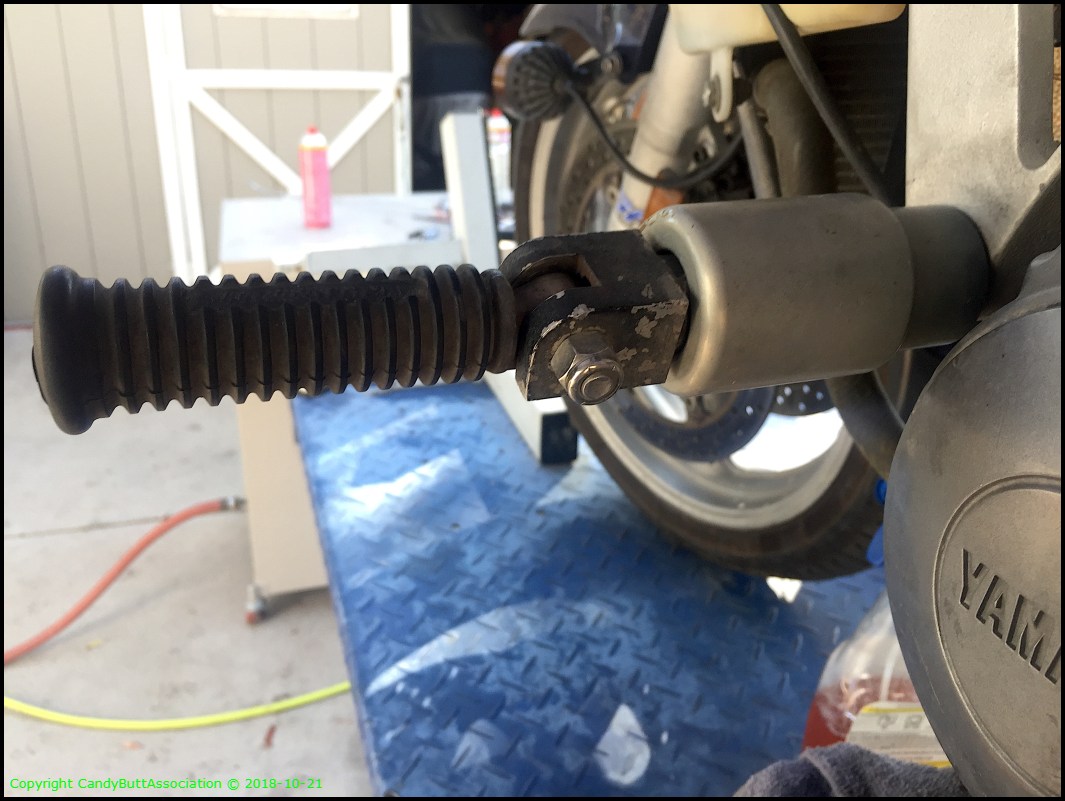
Pretty easy stuff IF you have machining capabilities.
Dang, these pix are way out of sequence!
.
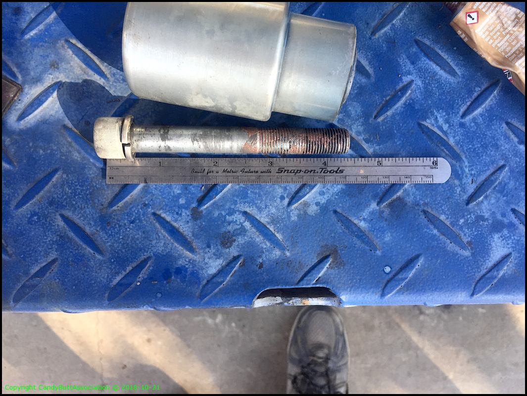
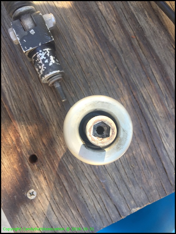
The washer 'stack' thickness determines peg location when tight. A bit of a guessing game but manageable.
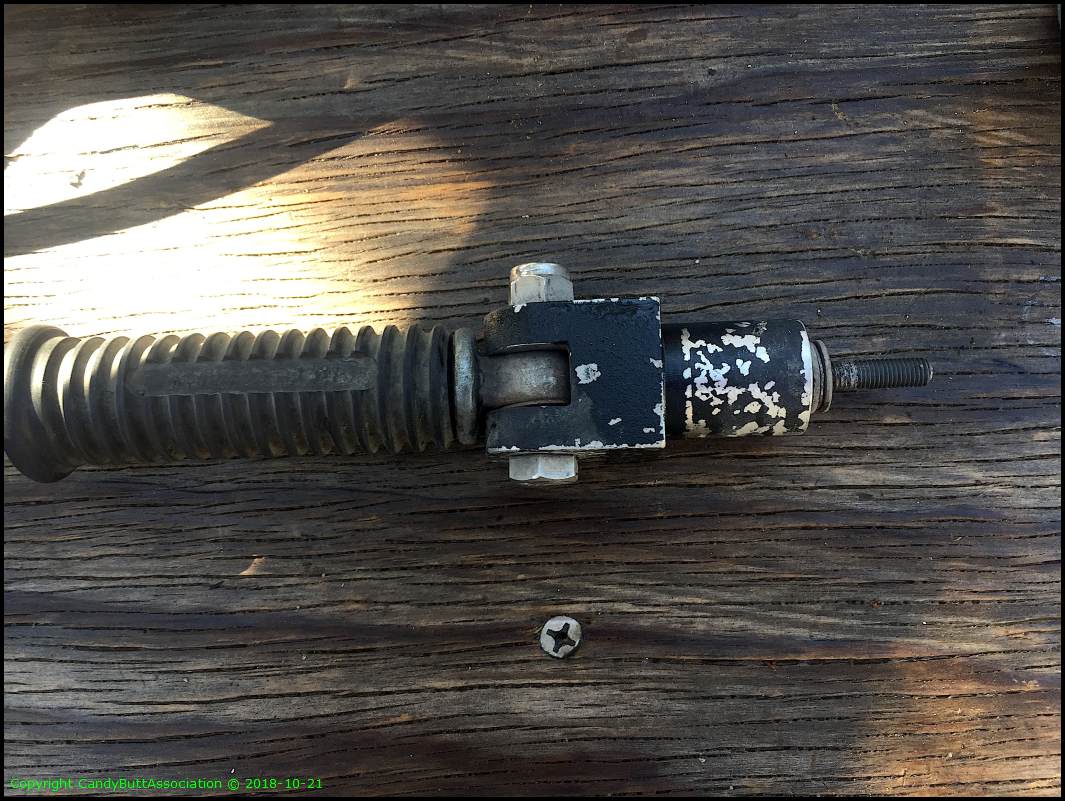
The head of the cap screw is drilled and tapped to allow peg threading.
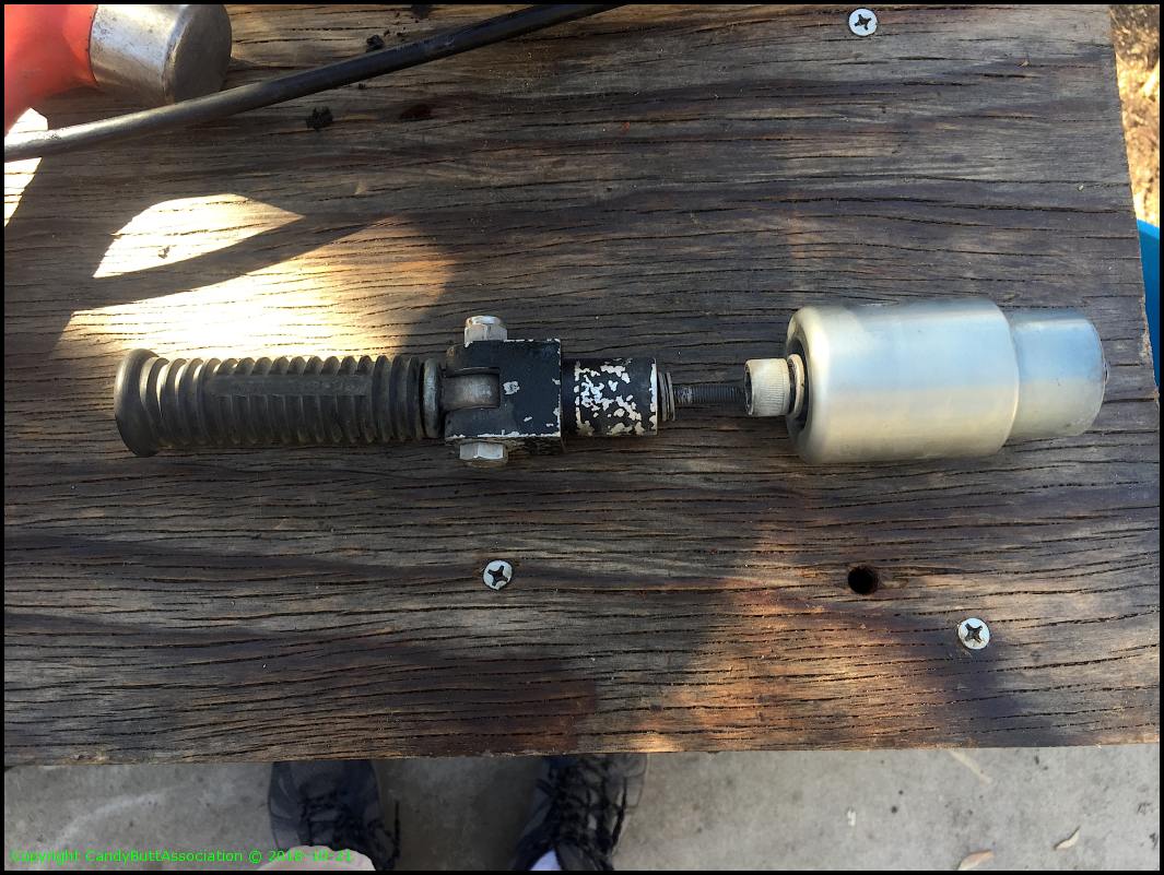
Like this.
Can anyone identify what's going on the with the cowling top?
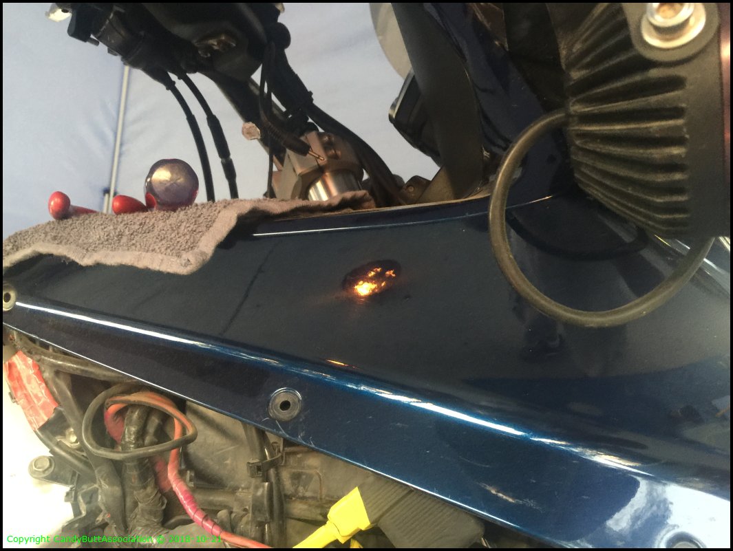
That's it for today..
2018-10-22 ValveReCheck
edit
2018-10-22 Valve Re-Check and CCT Removal
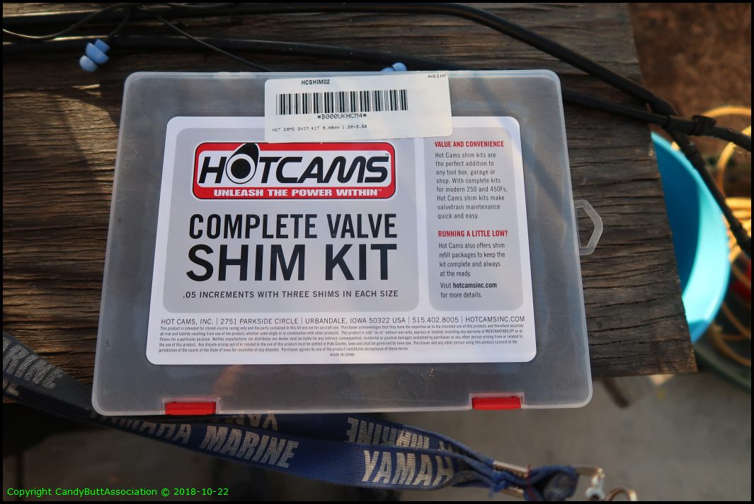
The HotCam shim kit arrived today. So let's get after the valve adjust/cam-removal.
First. Always double check your work. So I re-tested my original lash readings. No change, so good. Or I have a repeatable error.
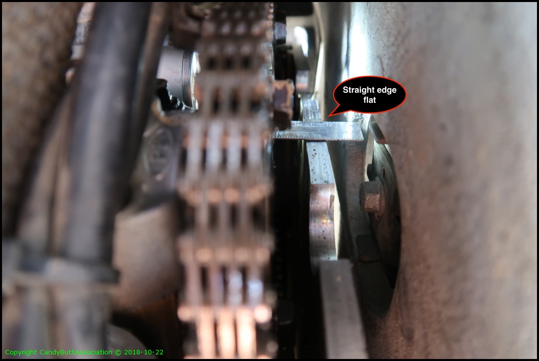
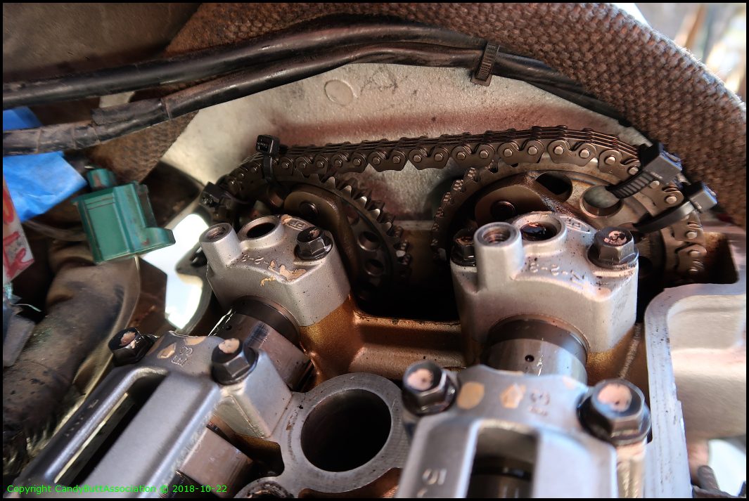
Align T mark with case. No pix but ensure cyl 1 lobes are facing 'outward' to each other indicating TDC.

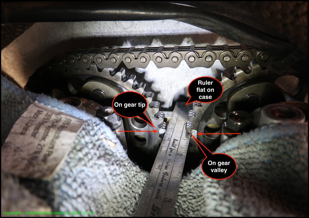
Very hard to see marks on outside of cam gears due to frame interference. Almost impossible with my eyeballs. I tried using a boreoscope camera no luck. A mirror I had was a bit to large to fit. But I was able to determine I was 'in-time' at this point. I marked the gears in relation to a straight edge resting parallel to the engine cases. Interesting to me that the exhaust tooth is on tooth 'point' and intake is on tooth 'valley'. Not sure what this really means.
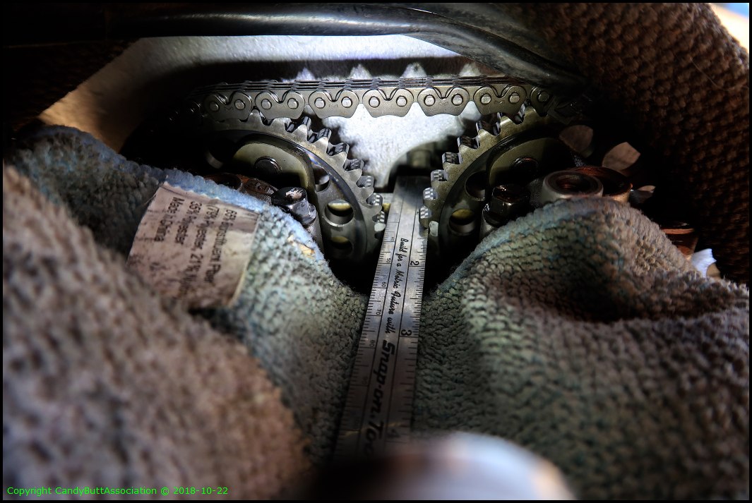
Another view.

.
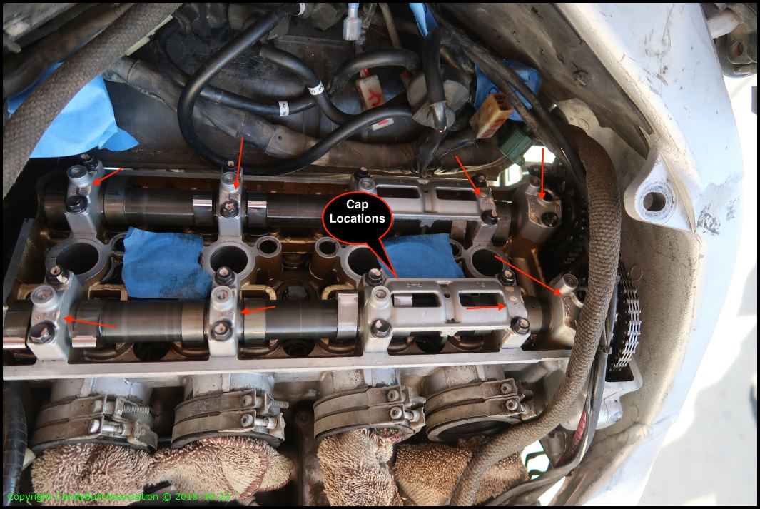
See speech bubble.
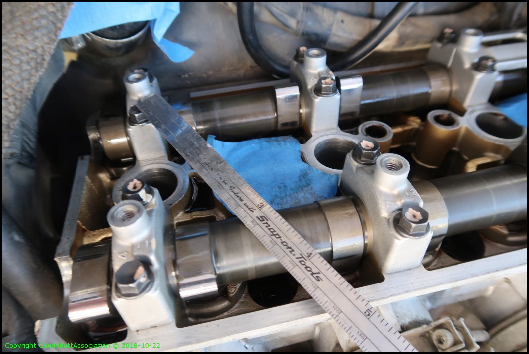
Not a great pic but #1 lobes are 'opposite' of each other indicating TDC.
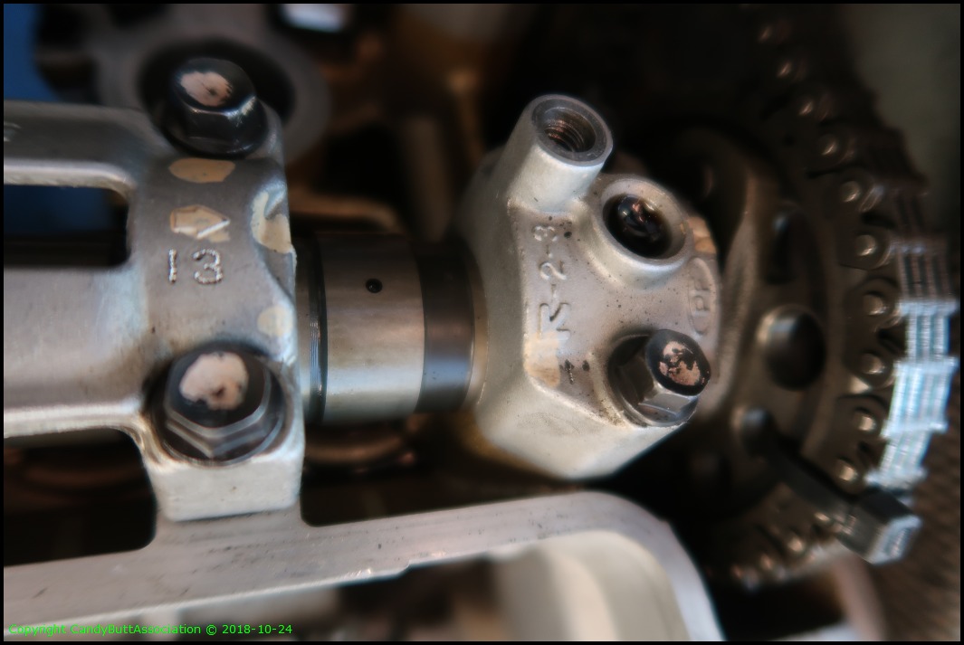
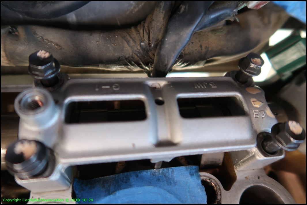
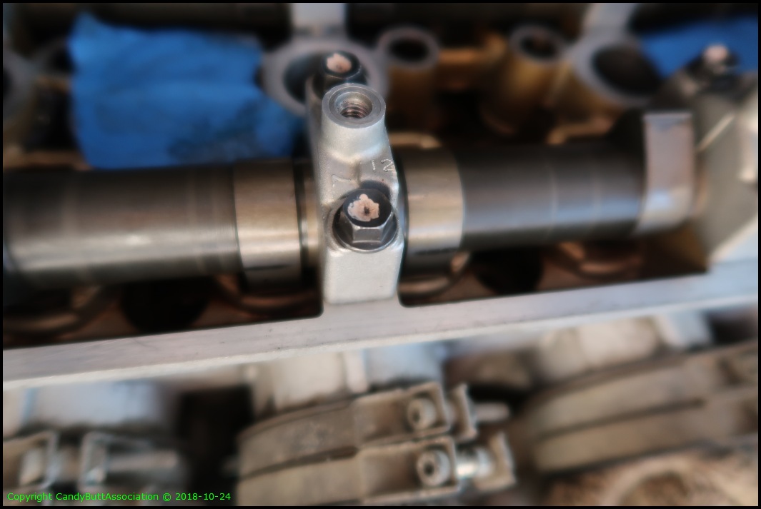
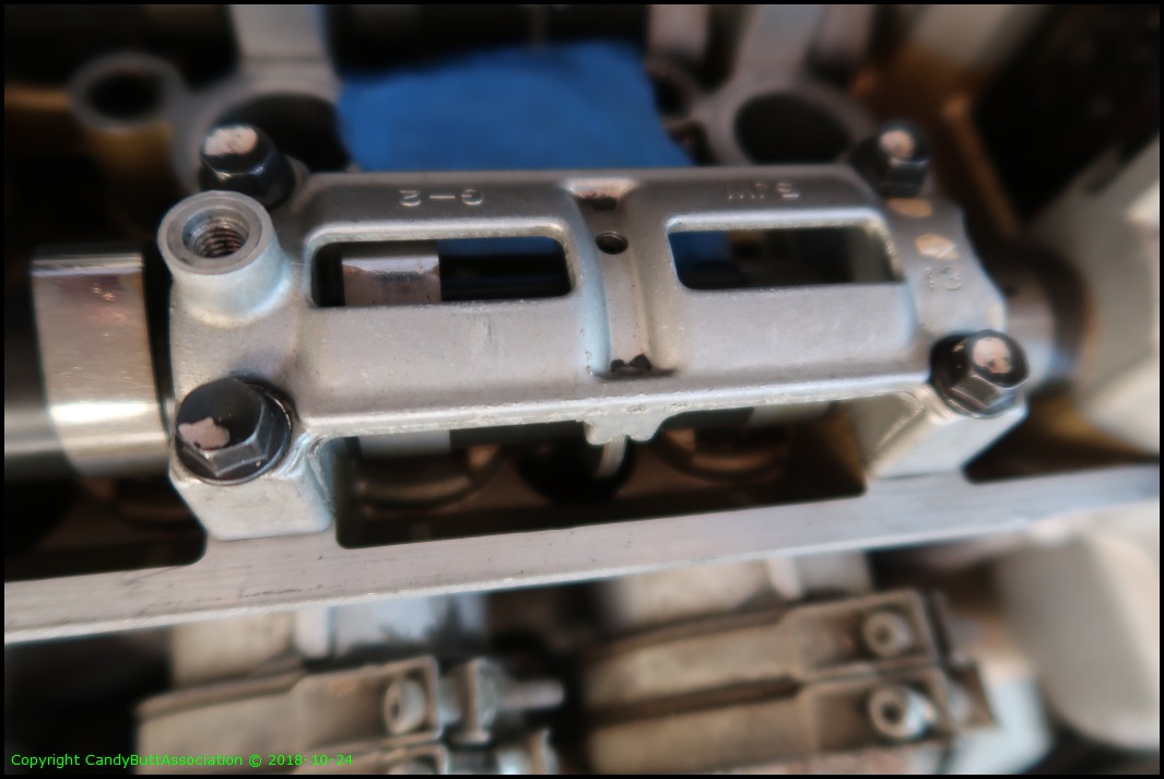
Cap locations on cam shaft. Zoom in, they are engraved.
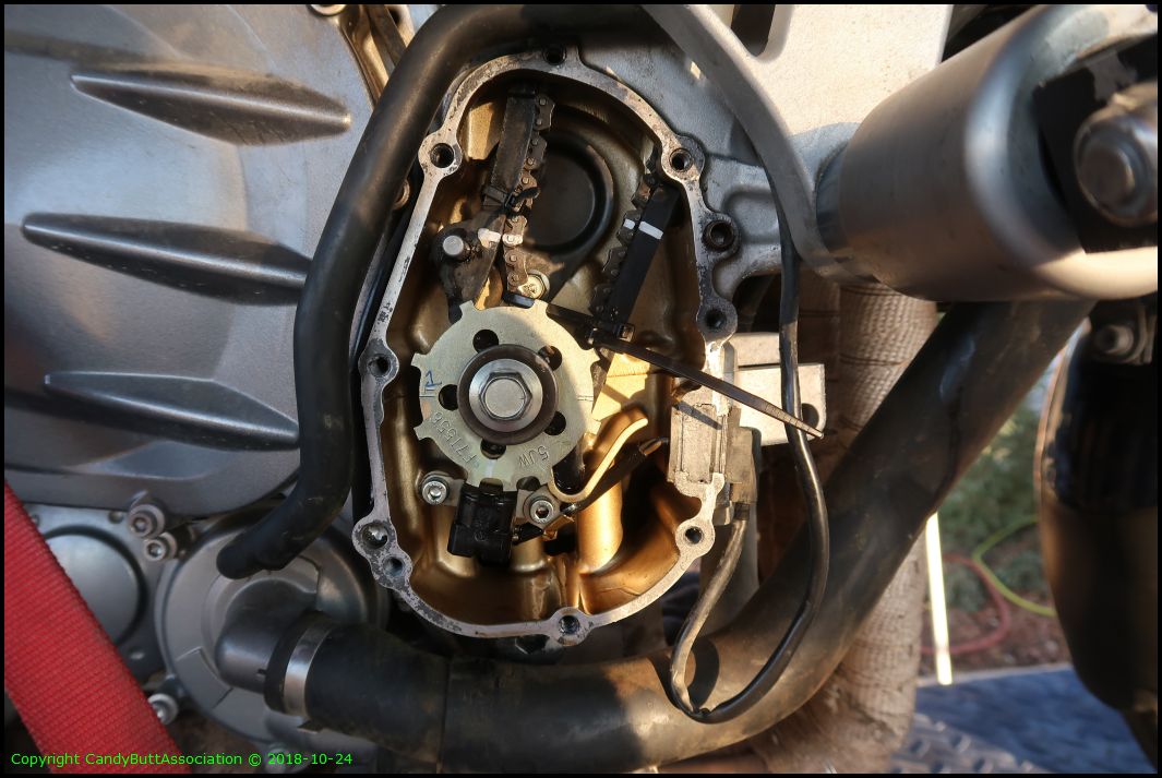
My CCT would not hold the 'relaxed' position so I clamped the screwdriver in place while I ty-wrapped the cam chain and removed the tensioner.
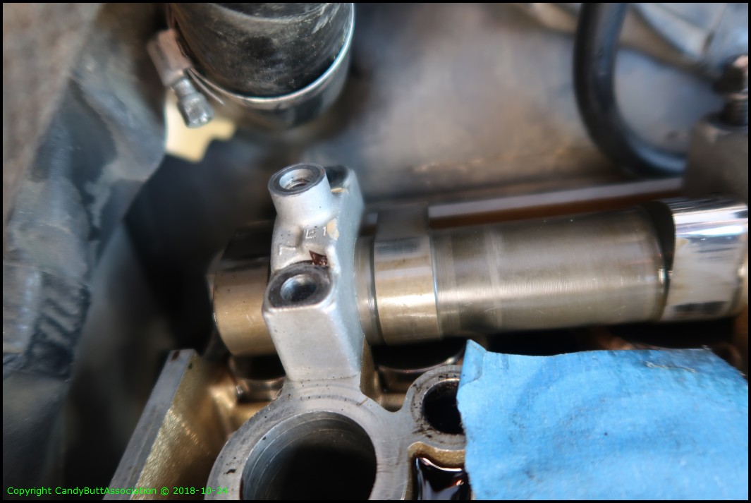
Relaxing the tensioner allowed me to re-install the intake side tensioner 'runner' dowel pin.

Yeah. I'm not jumping a tooth; ty-wrapped. Spoke with my local pro and he said he didn't worry about the crank gear slipping a tooth as he lifts only 1 cam at a time, using other methods to ensure the chain is slack enough to remove one cam but not get too loose. I need to see this in person to fully understand I understand. Do you understand?

Ok then. Top side chain locked down. But how the hell to lift cams high enough up to replace shims when everything is strapped down?
OK, I ran a calibration lab at an nuclear power plant. EVERY carbon steel surface was cleaned and preserved prior to storage. Not soo much HotCam stuff. A little disappointed.

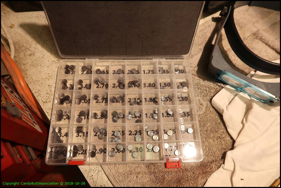
The kit.
The end for today.
2018-10-24 Cams Lifted
2018-10-24 Cams Lifted
Pretty straight forward, easy peasy. NOT. the cam cap bolts were t i g h t.
Pictures of caps for re-assembly later.
.
.

I lost a tooth on crankshaft sprocket. Very easy to do. Got it back on proper teeth. I think.
While wiggling the cams every now and then I'd get a instrument cluster sweep. WTFO? I think finally I've found my parasitic battery draw... This connector goes to Brodie's ignition relay.

Back to the caps.
Should have lifted battery leads earlier. No harm no foul.
.
.
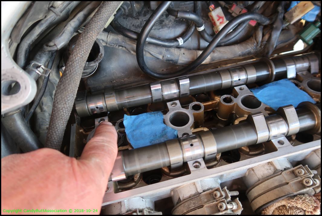
This bugged me. Why is the camshaft not sitting pretty in saddles? Because #3 is lobes down! Does this mean on reassembly one should tighten lobe 3 cap first?
.
Top-side can gear ty-wrapped.
.
.

.

2018-10-26 Valve Lash Adjusted
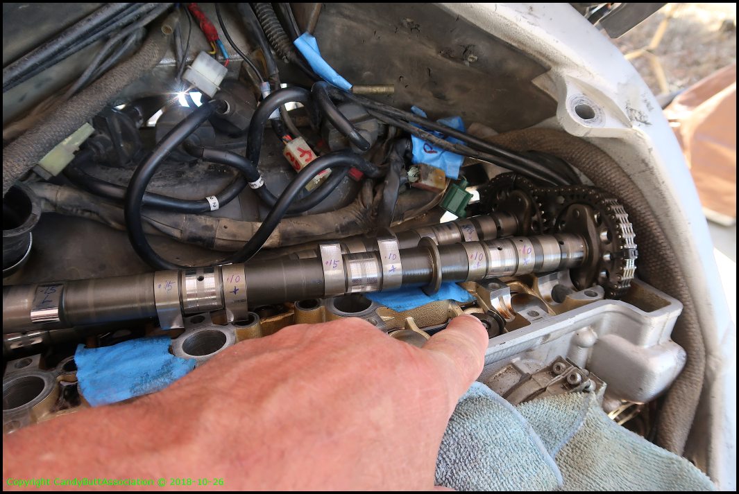
2018-10-26 Valve Lash Adjusted
Today was lash adjustment day.
My As-Found measured lash value.
Wrote values on camshaft to keep track of where and what I was working on.
First bucket removed. The shim sits on top of the valve stem.
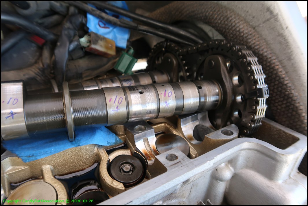
Like this.
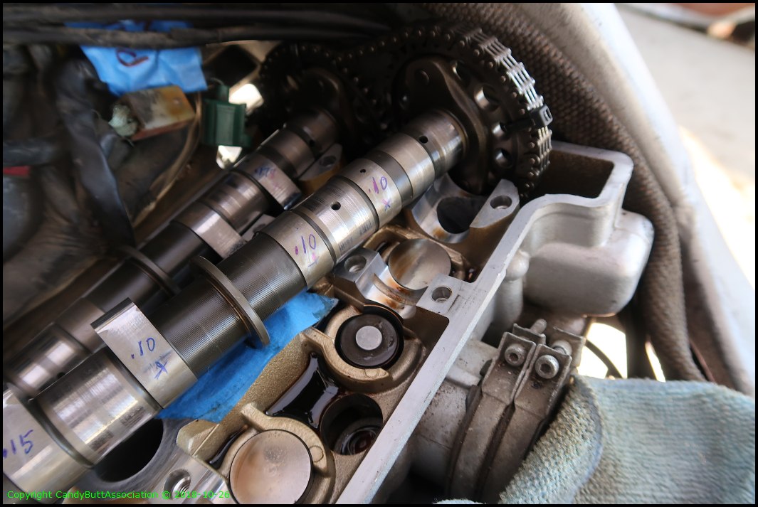
I used a magnetic 'pencil' to lift the bucket and shim up.

Fuzzy pic but you get the idea.
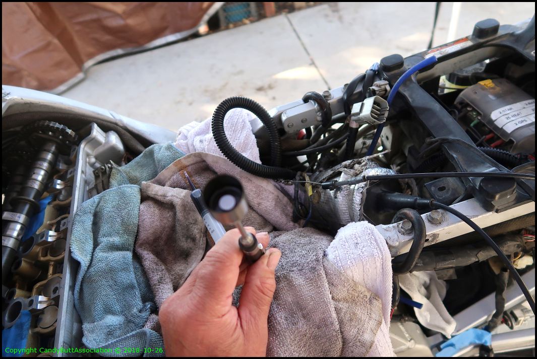
Another view.

All done!
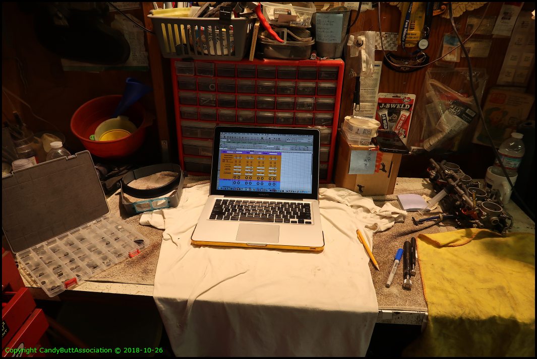
The control room.
Used up all my 1.75 and 1.80 shims!
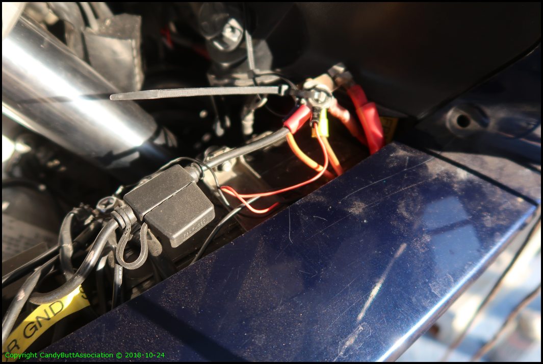
More pics of the corroded wires.
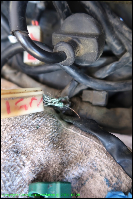
Geesh. This is nasty!

You got to keep them separated!
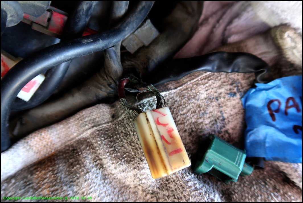
New connector is needed.

2018-11-02 Delay Relay & Aux Pp
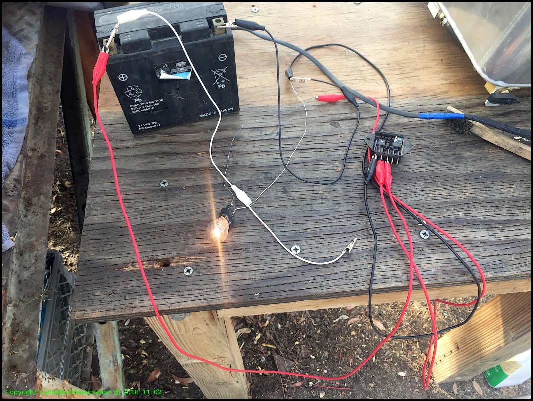
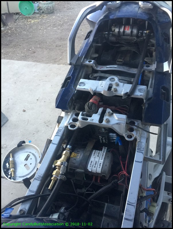
2018-11-02 Delay Relay and Aux Fuel Pp Test and Install
This is a programmable relay with time delay. 6 minutes after the trigger, it will shut the aux fuel pump off.
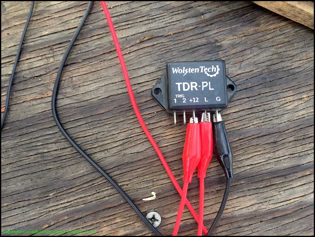
My test rig. Inside the relay you can see the timing pots.
I stole the original aux fuel pump set up off KrZy8 for Naomi, the 2013 FJR. Here's the new install.
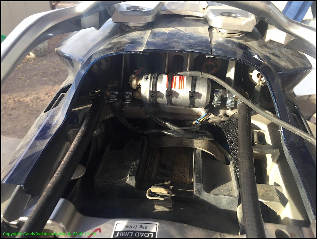
Still a need a female AN fitting to 5/16" barb. Just not sure what size the AN fitting is.
More to come..
2018-11-06 Final Valve Lash Measurements
2018-11-06 Spider Check
edit
2018-11-06 Spider and Brodie Harness Inspections
Gen 2 FJR's suffered from a 'spider' ground bite condition. The grounds were series looped together with increasing current load on subsequent to each 'spider'. In the pic below, the metal 'bridge' is called a 'spider'. A FjrForum member, Brodie, designed, built, and offered to the masses a heavy duty harness that could easily carry the increased current as each ground swum upstream to the ultimate ground.
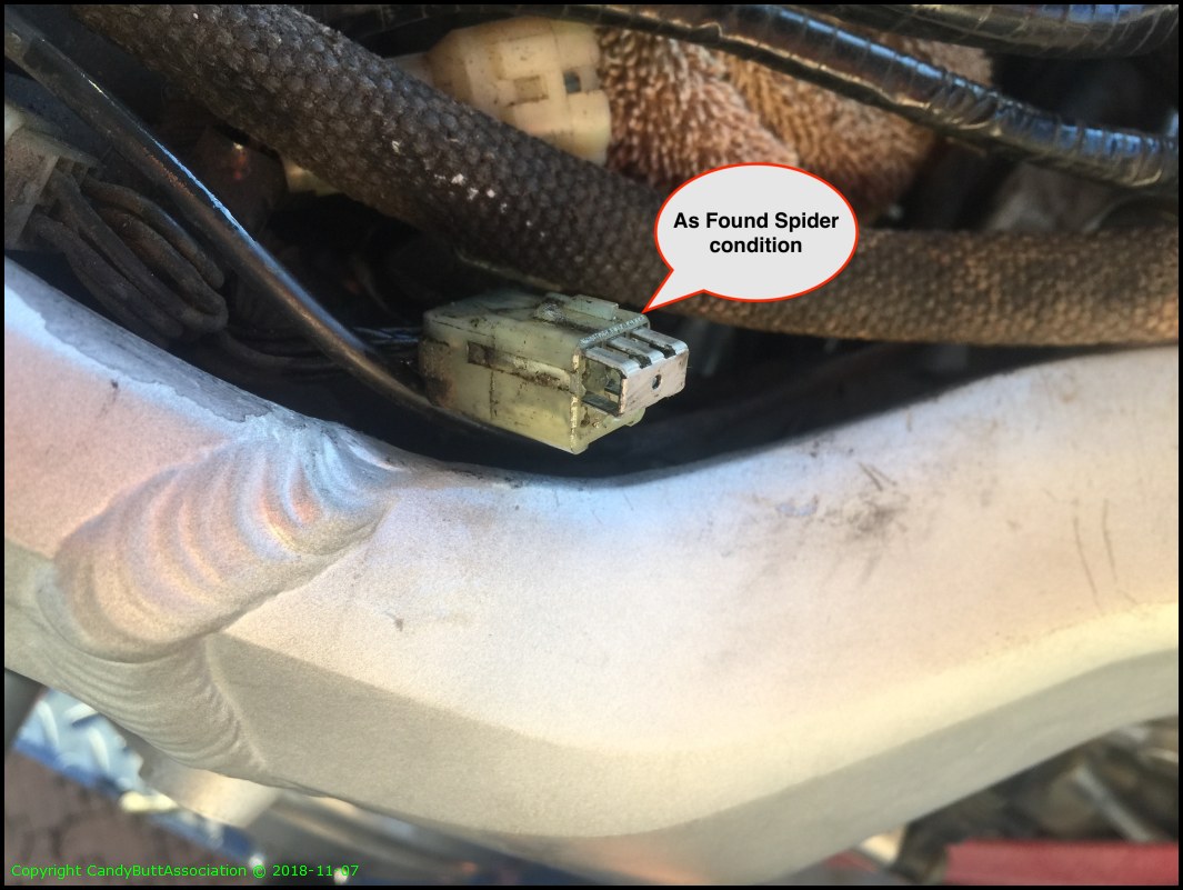
It's been years since I looked at these and though it best to inspect.
They were fine. A bit dirty and hard to separate, but the connections were A-OK.
This Brodie connection forward, LHS under the tank.

OK, I also bought a 'Brodie Ignition Relay' after my OEM relay left me stranded in Death Valley. Over the years and miles, the original connector and wires were very corroded and actually shorting.

Here is my fix. Jumper wires.
Had to use tags to ID wire color as I did not have 12 AWG wire on hand...

OK, enough. More later.
2018-11-09 Valve Cover Installation Notes
2018-11-13 Throttle Body and Airbox Install
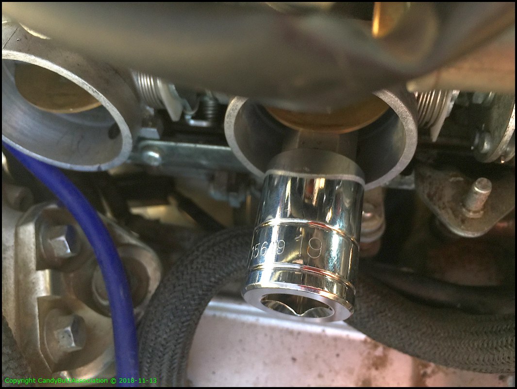
2018-11-13 Throttlel Body and Air Box Install
Installing the throttle body and air box is a real PITA for one human to do. Simply need more hands. Here the TB is staged for install.
Notes:
I gave up working the TB's for a bit and chased some more connectors.

.
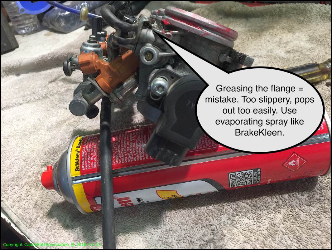
Used a 19 mm hex to hold butterflies open enabling throttle cable installation. As stated earlier, put those cables on first before TBodies!
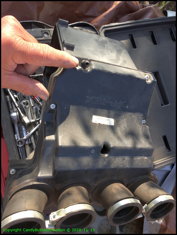
Replacement new to me airbox has nice flat, same plane intake boots. The OEM part on cyl 1 the boot was about 1/8" shorter than the other boots!

Installed cruise control throttle cable and found it had an interference fit. I bent the tang as much as possible and it still interfered. So ty-wrapped with two small tys.

Could not recall if this went to a hose or not.. Turns out it's just a drain. I added a filter to prevent contaminated air ingestion.
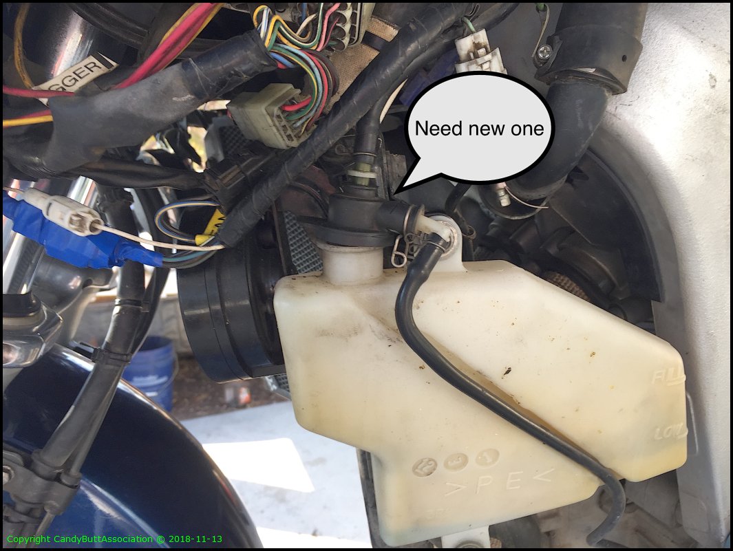
Note to self, need to buy new radiator rubber top.
Finally, throttle bodies and air box in place.

Side view.

Note to self need new.
Hit the starter button and the motor turns over, no valve interference, a good thing!