


As I mentioned in a prior thread, I just finished doing the 26k mile maintenance on my '05 FJR. The big ticket item on that schedule is checking the valve clearances (and adjusting if necessary). The best step-by-step description of the valve check job is this one, written by Dwayne Verhey back in 2004. Between that procedure and the scant section on valve check in the Factory Service Manual, any average Joe with half way decent set of tools and mechanical skills should be able to get the job done themselves and save a bundle. The best part is knowing it was done right and all the parts were put back together correctly. The following are just a few notes and tips on ways to improve the above linked procedure.
In preparation for this service, consider having replacement coolant and new spark plugs on hand, since you will have to remove both items to affect the valve check, and in all likelihood they will be due at this time anyway. You will also definitely want to replace the 3 o-rings on the coolant pipe. I found them at Home Depot and the best size matches were #14's for the two head connections and #17 for the thermostat.
I also took the opportunity to remove the PAIR system from my bike and install a set of WynPro PAIR block off plates. This is entirely optional and not related to the valve check except that you need to remove the PAIR valve assembly and plumbing anyway to check the valves, it was much easier to install the plates with the valve cover on a workbench rather than on the bike.
When preparing your bike for the service, you only need to remove the following:
Remove driver seat
Remove the left and right black trim panels at the rear of the tank, so you can tilt the tank.
Remove the lower right and left side faring panels including the lower front triangle panel. Leave the triangle panel attached to the right side panel.
Remove the screws in just the "A" panel (left side black panel behind the glove box with hazard flasher button in it). You do not need to remove panels B thru D. Also, you can leave the A panel hanging on the wires running to the fusebox and hazard switch. It won't get in the way. This is just so you can get access to the radiator cap.
Remove the two front bolts and tilt the tank back (doesn't need to be removed). You can tilt the tank back further if you remove the two electrical connectors on the bottom of the fuel pump assembly.
Hot tip: You'll want the tank to be half full or less. Any more and tilting the tank this high will cause a puddle of flammable liquid under the bike as gas runs back through the cap vent.
Use a tie-down strap from the metal bracket at the front of the tank (has some handy holes in it) run back to the luggage rack at the rear of the bike to hold the tank up. Do not pull back too hard as the limiting factor with the wires detached will be the length of your fuel line. This provides plenty of access room.
FJR stripped down for valve check: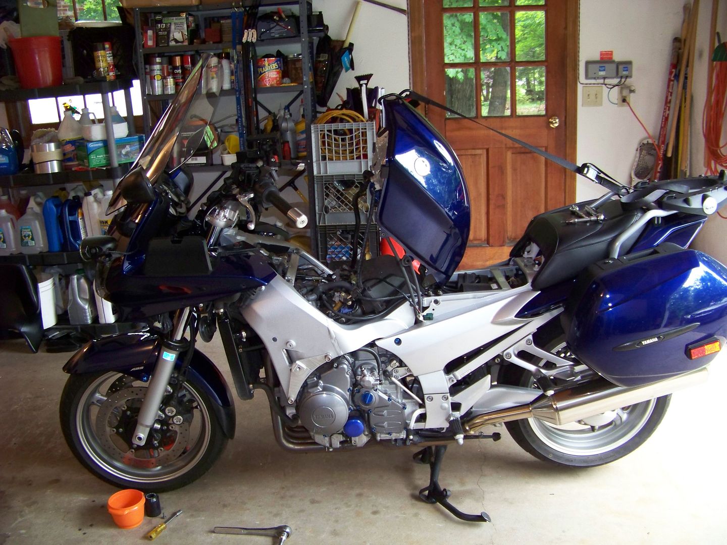
Closeup of tank support: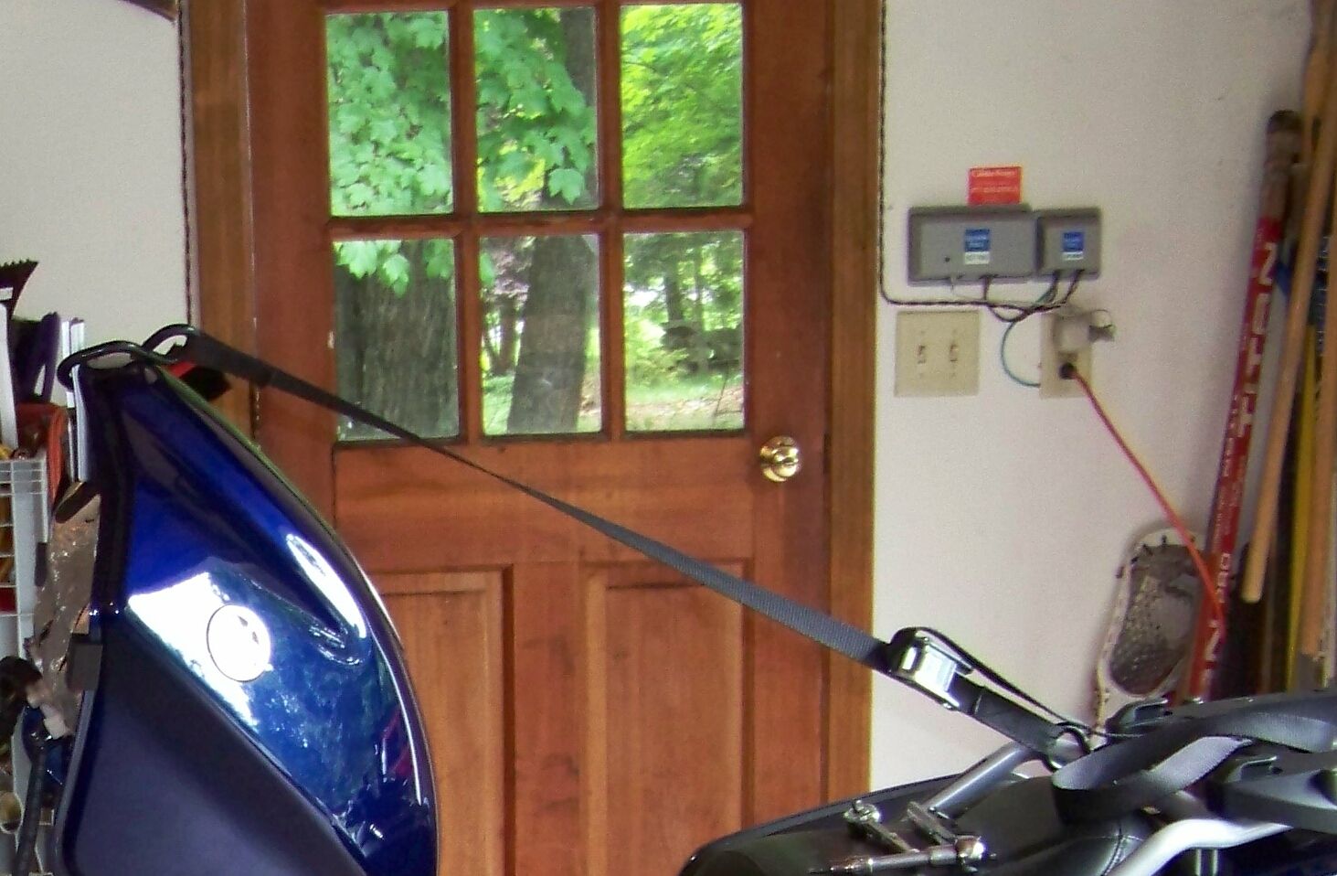
Access room under tank, and top of engine "before" picture: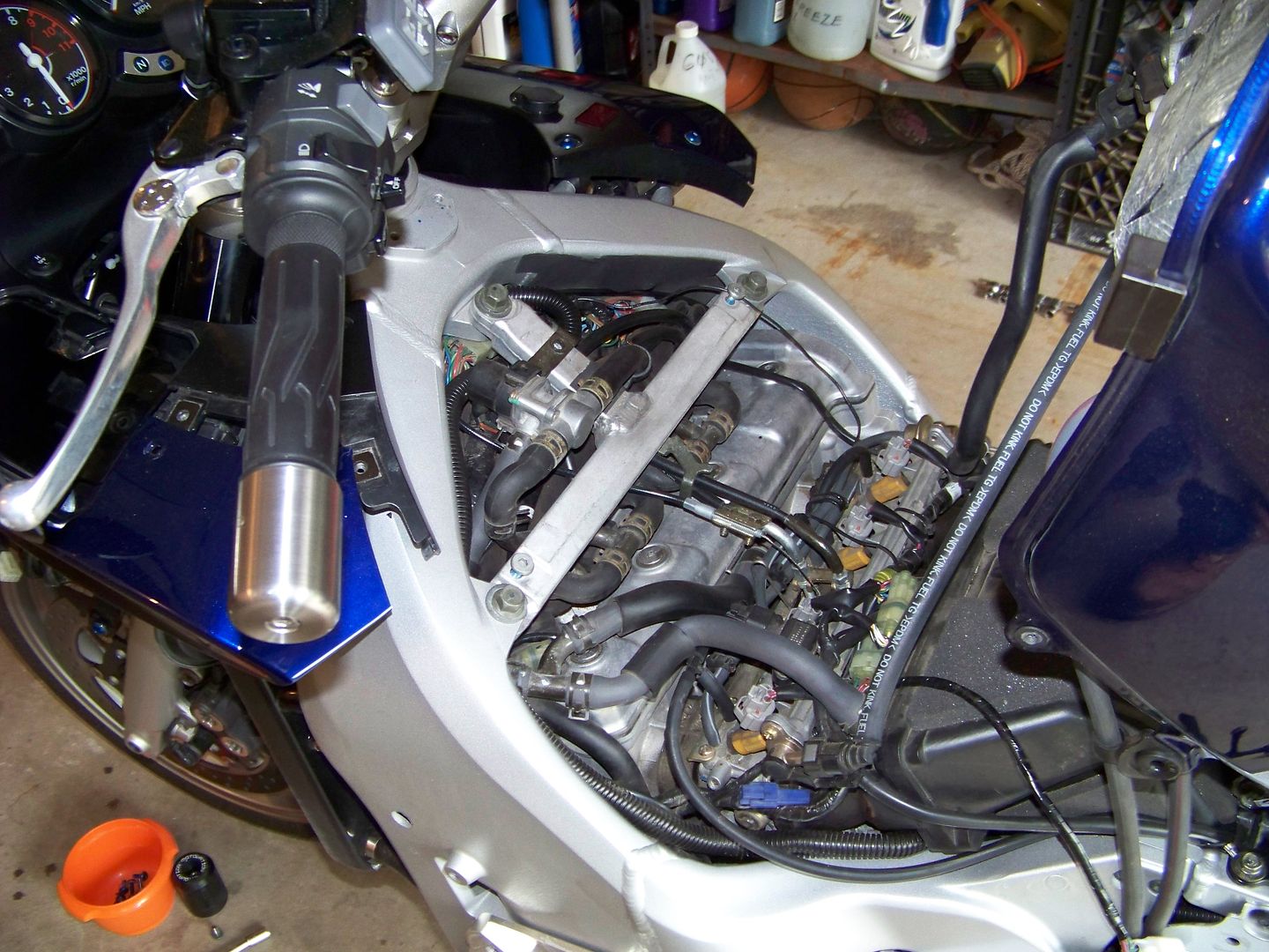
The only other body work that I removed (later on) was the left side saddlebag. This to allow me to turn the rear wheel by hand, with the bike in 5th gear while peering under the tank, in order to index the engine for the checks on each cylinder. This is a highly recommended way to turn the engine so you do not have to remove the right side timing chain cover (aka oil pump cover) unless adjustments are required. It was quite easy and gave good control of the position.
N.B. If you do decide to remove the right side timing chain cover, see this note about the chain guide slipper dowel pin that gets stuck in the cover. It may mess up your valve timing!!
Remove the Tee-Bar and all the PAIR stuff (Pair valve all hoses, disconnect wire).
Bye bye PAIR junk: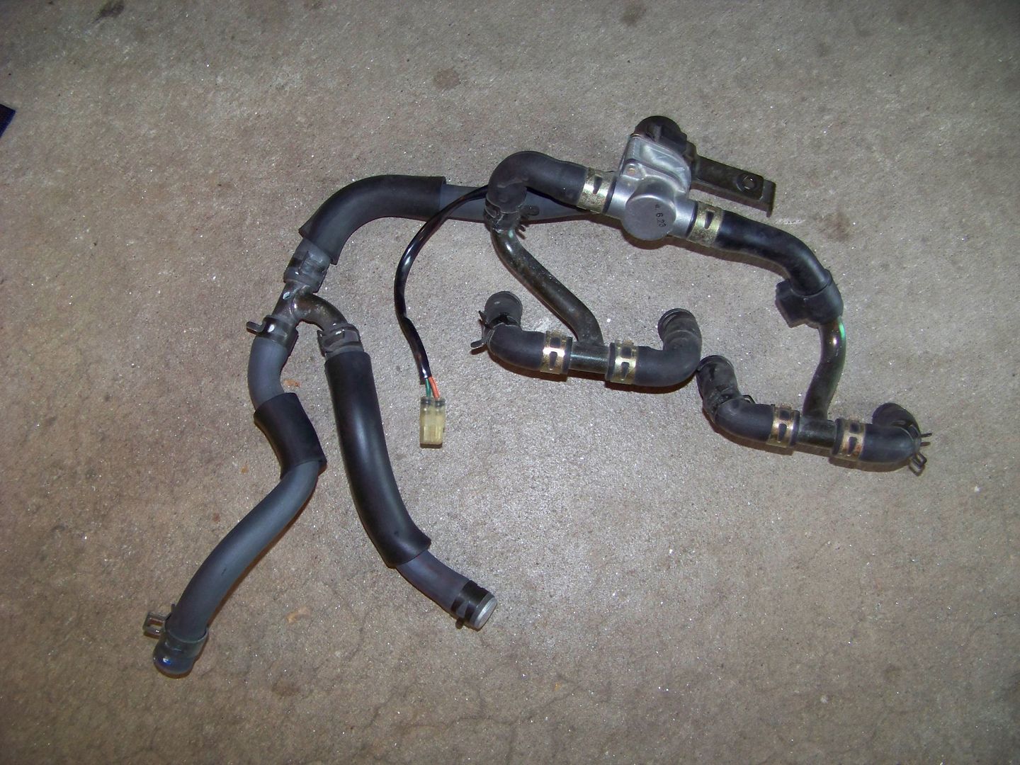
Detach the spark plug wires and push them over to the side. Remove the rubber flap that covers the front of the head over the top of the thermostat. (Not sure what it's for, maybe protect the wiring from the heat of the thermostat).
Ready to remove Coolant pipe: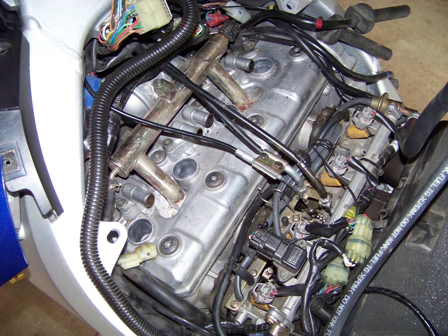
Before removing the coolant pipe take some time to clean up the area, especially the recesses where the rusty coolant pipe attaches down to the head. There was a bunch of junk down in there that I was able to get out by shoving a length of vinyl hose onto the crevice tool of my shop vac and duct taping it up.
When removing the coolant pipe, after removing the 4 screws (2 torx heads, 2 allen heads), first pry the thermostat housing away forward, then after free of that you can pull up (and wiggle) to get the two connections out of the head. They will be difficult to remove as you pull the o-rings past crusty buildup. This is why you will be needing to replace these o-rings. I couldn't believe how rusty and cruddy these connections were on such a relatively young bike.
With the pipe removed, time to clean-up again. Get as much of the cruddy build-up removed as possible before exposing the inside of the engine. Try to vacuum out any debris that falls into the waterjacket area of the engine
Looking into the cruddy coolant pipe holes: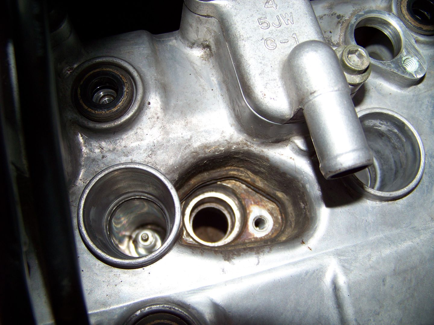
Now that everything is cleaned up, time to remove the head cover. The first "trick" learned here (thanks Constant Mesh) is that the front right side of the valve cover is inhibited from removal by the black plastic shroud above the radiator. Here you can see the edge of the black plastic shroud where it interferes with the front right edge of the valve cover: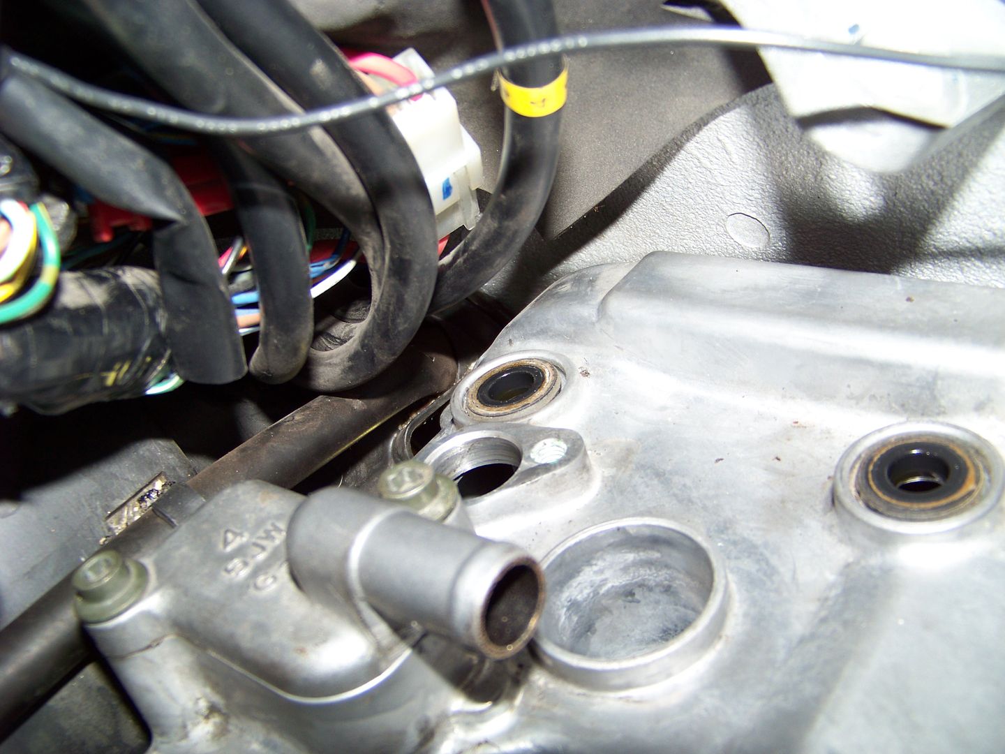
You'll want to pop that shroud forward to allow the cover to come out. Here you can see the head peeking through past the offending shroud being levered out.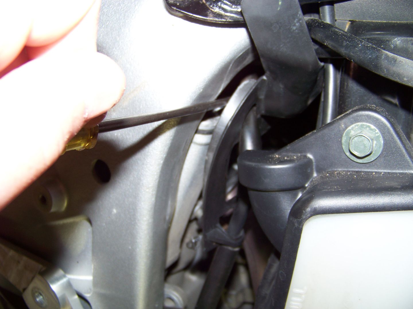
The second "trick" learned was to disassemble the throttle twist grip assembly and pull the cables backward through the frame so there is enough slack over the top of the head. You don't need to pull them all the way through, just far enough so they loop backwards away from the engine.
Once the valve cover was removed, everything went pretty much "by the book". I used inch base feeler gauges. It may be advisable to buy a set of metric feelers. In either case you'll want to use them in a go/no-go fashion, starting with the minimum clearance spec. If you can slide the gauge in, the gap is at least that big. The actual clearance is somewhere between the last go gauge and the 1st no-go. On that last "go" measurement, make note of how easy the gauge slides into each position as an indicator of where in that .001" range the actual measured value is for future reference.
All 8 of my intake valves were between .006" and .007". But 3 of the 8 were on the tight side, while the others were looser. Knowing the positions of the tight ones will be important in 26k more miles. My exhaust valves were all in the middle of the spec range, so no worries.
And finally, here's the "beauty shot" of my engine, the "after" picture with the spiffy new PAIR removal block off plates installed. Not as sparkling clean as Useless Pickles' engine, but certainly better than at the start.: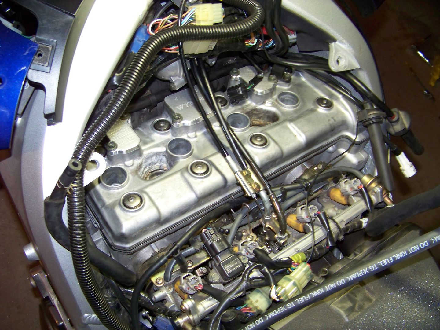
- Home
- Forums
- Ride Reports
- MotoBikes
- Restorations
- Wrenching
- 1963 BMW R69s
- 1969 BMW R60/2
- 1978 Yamaha 125
- 1979 KZ1300
- 1979 Kz1300 - Bob's Beauty
- 1981 CBX SuperSport
- 1981 Kz1300 Model A3 - Chocolatie
- 1984 Ford F250 XL
- 1987 ATK
- 1987 MowieMowie
- 1987 RotoTiller
- 1988 Honda Accord Lxi
- 1990 BMW RT100 - Barrie
- 1991 Harley Davidson FLHTCU
- 1992 Johnnie Deere
- 2000 YZ426
- 2002 Dodge Ram
- 2006 Carson RacerX Trailer
- 2006 Host Camper
- 2006 KrZy8
- 2007 Wabs
- 2012 KTM 690R
- 2013 Naomi - FJR 1300
- 2014-08-01 Air Compressor - Sears
- 2017 Kioti
- 2018 Toy Hauler
- 2020 Honda Fit
- 2021 Miscellaneous
- 2024 Log Splitter
- 2024 NeoDyne MC Lift
- 2050 test
- Lil Trlr
- Eats
- RIP
- PC Not
- Cages
- Test
- FJRF Best
- For Sale