


Hard to juggle "Feej Time" with "Real Life" and I'm wondering if I'll meet my self-imposed Halloween deadline to be finished with the project.
My parts order from Gary consisted of a set of gaskets and new camchain, which will be installed with the Manual Cam Chain Tensioner from A.P.E. (thanks, Brodie)
After working on "Frankenbike" for 10 months now, I've decided that WITHOUT A DOUBT, the most important tool to have for this kind of project is a good digital camera to document your work. It's invaluable in setting a "benchmark" where all the original parts should be, to have a comparison to the final installation.
Oh, I can not emphasize how much easier it is to work on the motor with no frame in the way.

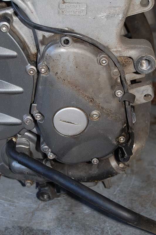
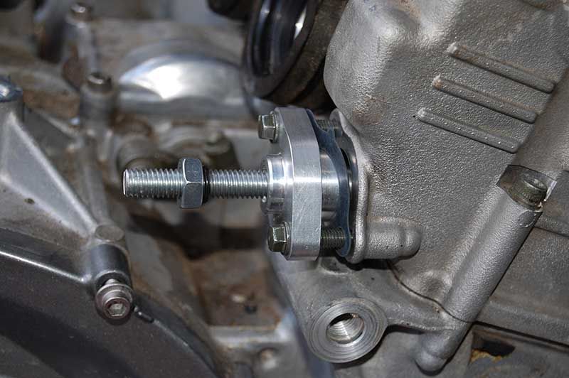
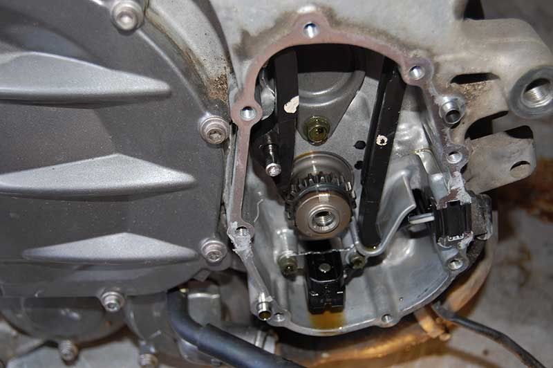
This is the cam chain and timing rotor cover. It must come off to remove the ignition timing rotor to be able to remove the chain. The hex bolt at the top (already removed) and at 1 o'clock are longer than the rest. Keep that tidbit of information handy.
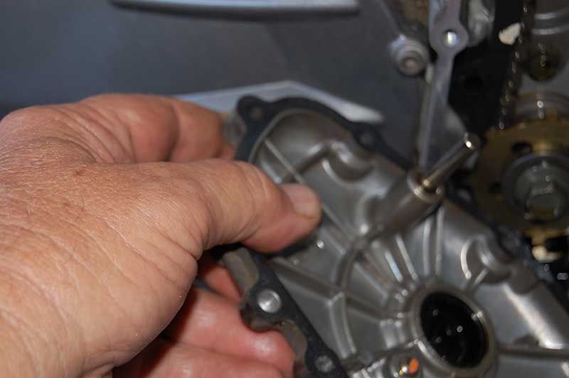
The dowel pin that locates the left-side chain slipper will probably come out with the cover. It's a very tight fit in the cover and oil on the pin will create a vacuum to "lock" it to the cover. Since this pin positively controls the position of the slipper, it is imperative that you do NOT rotate the motor until you pull the pin from the cover and replace it in the engine block to anchor the slipper. It's the one the CCT presses against to tighten the chain and WILL slip if you move the chain in any direction. DO NOT rotate the motor until that pin is back through the bottom of the slipper, in the block.
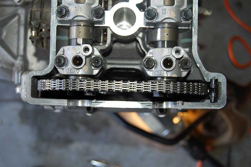
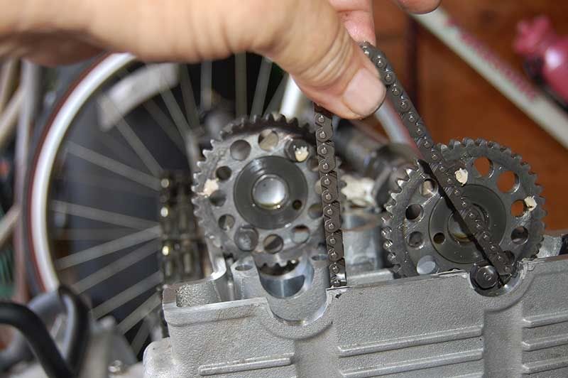
Top of the cylinder head, looking down at the cams and chain. That chain is not coming out with the cams in place. They've got to come out.
At this point, before you can pull the cams and remove the chain, the CCT must be de-tensioned, documented thoroughly in other threads. I'm replacing the CCT, so there's no reason to de-tension...simply remove it.
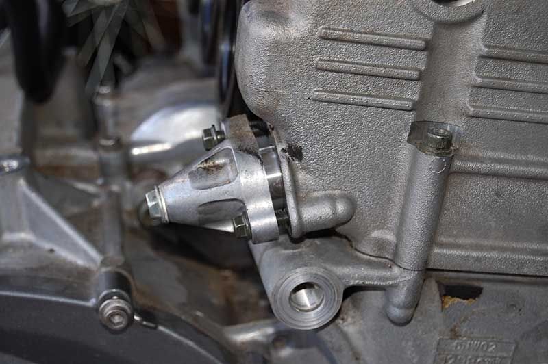
In its place goes the manual CCT from A.P.E. Notice I've backed the adjuster rod all the way out to there's zero tension on the chain. Also note the new gasket. Why tempt fate?
Cams out of the way, old chain in hand.
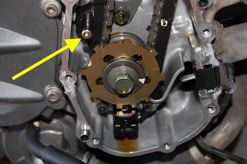
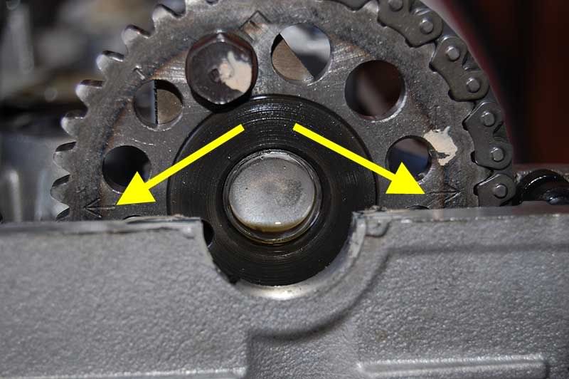
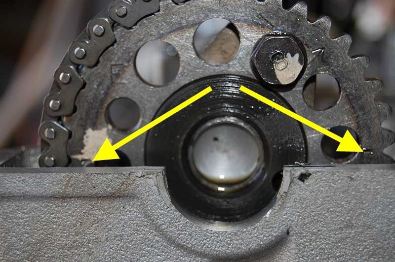
The timing rotor must be removed to get the chain off the crank sprocket. Anecdotal evidence suggests (with the motor installed) putting the bike in gear and blocking the rear wheel to be able to get the bolt out to remove the rotor. With my motor out of the bike, I didn't have that option, but as I discovered on my original motor, the bolt isn't THAT tight...a sharp hit on the ratchet handle with the palm of my hand broke the bolt loose with no problem. Also in this picture, I highlighted the locator pin from picture #2 that came out with the cover, here put back where it belongs through the adjusting slider into the engine block.
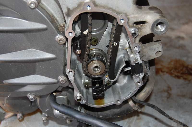
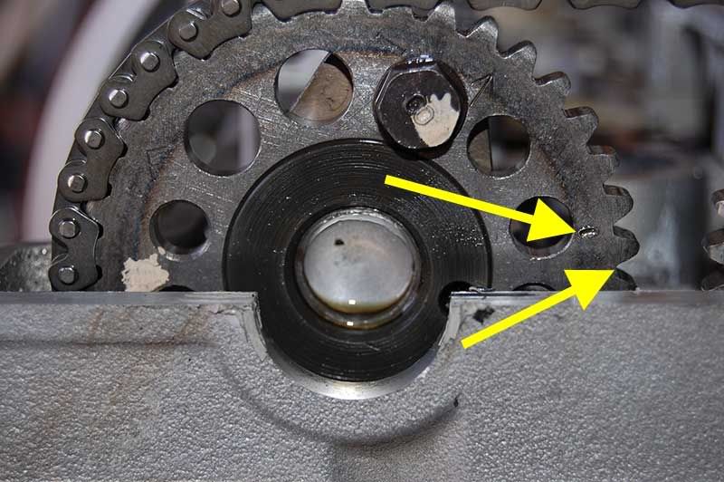
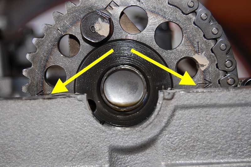
And here's the crank sprocket and chain with the rotor removed. Note its narrow diameter. THAT'S why a loose chain from a faulty CCT so easily allows slipped timing. There's just not a lot of sprocket "grabbing" the chain. Also note the clearance between the chain and the right chain guide slipper is VERY close. I slid it up and out of the top of the cylinder head to facillitate chain removal and replacement. It slides in and out without any fastener removal. It's simple "trapped" in the block by casting shapes.
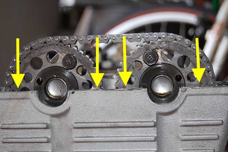
Chain gone, slipper back in, ready for chain and cam installation.
Now comes the most critical part of the reassembly...getting the cams back in IN TIME with the crank position. With EXTREME diligence, I made 100% sure the timing mark on the rotor lined up correctly with the mark on the block casting, wrangled the cams back in place, snugged down the cam holders and put tension on the CCT. Even with the utmost care making SURE everything was lined up correctly, here's what I got on my first try....intake retarded 1 tooth on the sprocket.
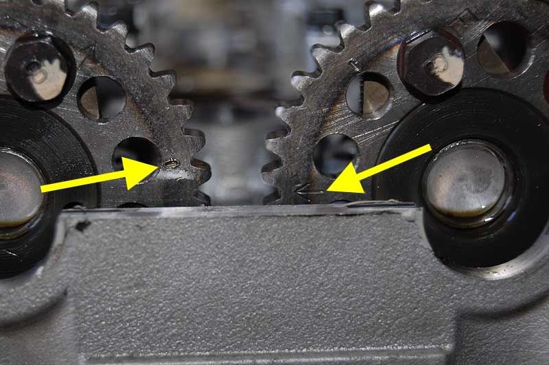
I was dumbfounded! I had been SO careful to line everything up and it's outta time! I double-checked everything. Rotor lined up at TDC? Yep... Exhaust cam lined up? Yep...
Intake cam lined up? Nope! One tooth off!
Release ALL the tension on the manual CCT, move the intake cam one tooth and voila!
Did the exhaust cam move? Nope!
Rotate the motor by hand two full revolutions.....any binding? Nope. Any mechanical "clunks" indicating unwanted collisions? Nope. Recheck. Looks good. Another two revolutions to be sure. Check again...looks good!
Just to convince myself, I did the "revolution" check several more times. This sucker is in time.
Lesson(s) learned this afternoon?
1 - Take the motor out of the frame to work on it. SO much easier!

2 - No matter how careful you are, and trust me I WAS careful, it's a snap to get a cam in 1 tooth off. Probably explains the forum reports of cam timing off after valve adjusts.
3 - Do the exhaust cam first! There's no slack on the chain run going down to the crank sprocket, so install and time the exhaust cam first. It's nearly impossible to retime the exhaust cam with the chain attached to the intake cam, so get your exhaust cam in place and in time FIRST. Then it's easy to get the intake cam lined up correctly.
4 - Double check. Then triple check. Then quadruple check. If you don't you'll be right back where you started 10 months earlier.
'Howie