- Home
- Forums
- Ride Reports
- MotoBikes
- Restorations
- Wrenching
- 1963 BMW R69s
- 1969 BMW R60/2
- 1978 Yamaha 125
- 1979 KZ1300
- 1979 Kz1300 - Bob's Beauty
- 1981 CBX SuperSport
- 1981 Kz1300 Model A3 - Chocolatie
- 1984 Ford F250 XL
- 1987 ATK
- 1987 MowieMowie
- 1987 RotoTiller
- 1988 Honda Accord Lxi
- 1990 BMW RT100 - Barrie
- 1991 Harley Davidson FLHTCU
- 1992 Johnnie Deere
- 2000 YZ426
- 2002 Dodge Ram
- 2006 Carson RacerX Trailer
- 2006 Host Camper
- 2006 KrZy8
- 2007 Wabs
- 2012 KTM 690R
- 2013 Naomi - FJR 1300
- 2014-08-01 Air Compressor - Sears
- 2017 Kioti
- 2018 Toy Hauler
- 2020 Honda Fit
- 2021 Miscellaneous
- 2024 Log Splitter
- 2024 NeoDyne MC Lift
- 2050 test
- Lil Trlr
- Eats
- RIP
- PC Not
- Cages
- Test
- FJRF Best
- For Sale
Candy Butt Association
World's Wimpiest Riders
You are here
2012-06-14 Low Volts, Charging Circuit

Forums:
First posted on fjrforum.com
Been noticing max VDC decay on 8500 radar detector / voltage meter. Hmm.. getting ready to leave on fairly decent CBA ride to Castlegar, BC. Maybe I should test just how good/bad this potential problem is?
No Load
Idle VDC = 13.2
5000 rpm = 13.5 vdc
HID Lights On
Idle VDC = 11.8
5000 rpm = 12.3
Funny thing is, last week, taking a fairly long ride, 120 miles each way, I occasionally saw the desired 14.3, 14.5 VDC..anyway,
Hmmm. Maybe the stock stator, at ~150k miles has finally started to decay? I have a 5k mile stator from an 08 sitting here. Do the swap.
No real difference in readings.
Any chance it's as simple as a failing battery dragging the charging circuit down? It's at least 3 years old, ~40k miles.
Or is it going to be just my luck that the crashed engine that had road rash on the alternator cover took a hit hard enough to de-magnitize the rotor?
It sure seems like my 150k mile-non-crashed-engine 'sucks' the stator in place much firmer than the 'new' 8k crashed engine..
I'll throw a new battery at it tomorrow, don't mind spending the bucks. Hopefully the 'batteries are us' peeps have one for the FJR.
Funny thing, the OEM battery I replaced 'just because'. It's been working flawlessly in a Sears riding mower...
I am waaay open for relevant suggestions and ideas..
Thanks In Advance...
Castlegar awaits in balance..
From Ionbeam, various posts on FJR forum..
| With a good charging system, and a healthy, properly charged battery I would offer these guidelines for sustained voltages: ≤12.8 volts at the battery terminals – the charging system is over taxed, the battery is being discharged, and the stator is in danger of being permanently damaged. 12.8 to 13.2 volts – entering the danger zone, the battery is no longer being trickle charged and the stator is being taxed to the limits. 13.2 – 13.7 volts – sustainable, the stator is taxed but the battery is being charged. 13.7 to 14.5 volts – schweet |
| Is the ES toast? Remove the stator wires from the R/R. Set your volt meter for AC volts and the range to accommodate readings up to 75 VAC. Start the engine. Using great care not to cause shorts or even more important, not to touch the wires, measure any stator wire to any stator wire. At idle the voltages of the stator wires should be within +/- 2 volts of each other. Passing this, crank the RPMs up to 5k RPMs. Measure the stator again. Any wire to any wire should be >60 volts and the readings within 3 volts. Passing this the stator is good |
| Over the past several weeks I’ve noticed that my radar detector’s volt meter reading would drop down into the 11 volt range every once in a while, but would recover back to ~13.6 volts. Everything seemed to work fine and there was no problem starting so I chose to ignore the irregularity. Yesterday, less than a week from EOM my stator 100% quit while I was out running errands. While parking my bike at the first stop I noticed that the headlights reflection in a store’s window were a deep yellow. This prompted a quick glance at the volt meter – 11.2 volts. Oh phuck. Leaving the store Feejer started right up with little drama so I went on to my next stop but parked so that there would be some chance of bump starting it should things continue to get worse. Leaving this stop the electrical system did a full drop-out and reset the meter but on a second try it started. Now came the anxiety of making it home before I ran out of volts. About 2 miles from home my detector’s volt meter was reading 10.4 volts making it a close call if I would get home. I have confidence that the coils will continue to fire down to 9.8 volts but I’m not sure how the Injectors or Fuel Pump will behave. When I went over a frame shaking bump the meter jumped up to 11.2 volts, assurance that I would make it home and a tip-off that the problem could be a loose connection. I was able to zip into my garage with no further drama. Off comes panels C and D. The battery terminals are just a tiny bit loose, not enough to cause my problems directly. A real volt meter shows 11.2 volts on the battery with the engine off. I started the engine and the voltage dropped to 10.9 volts reflecting the power consumed starting the engine. Revving the engine to 5k rpm produced zero increase in voltage. Not good. I plugged my trickle charger into the permanently attached pig-tail for a quick feeding. Off comes panels A & B as well as the lower fairings. On my Gen I, I now have access to the rectifier/regulator (RR) plus the stator and battery connectors. A quick inspection does not show any problems with the wires or connectors. I back probed the heavy battery wires attached to the RR and started the engine. Still no charging voltage right at the RR. I did a voltage drop measurement from the + output of the RR to the + terminal of the battery -- 0.2 volts which is good. I did a voltage drop test to the negative terminal of the battery -- 0.3 volts, acceptable. I did a negative voltage drop test to the engine -- 0.5 volts, not good but not related to my failure. The excessive voltage drop seems to be at the lug crimp where the cable attaches to the engine block. Another day, another time I will address this problem. So, the problem may be a short in the main harness, a bad RR or a bad stator. I unplugged the battery wires from the RR and with the engine running, a known good battery connected to the RR terminals I checked the battery voltage. There was still no charging voltage even with the whole motorcycle electrical system out of the picture. I won’t have access to a meter that can accurately measure fractional ohms until Monday so I did an AC voltage test on the stator. All three wires should read ≥50 volts AC, any phase to any phase when the engine is running at 5k rpm. Two phases were just a bit over 48 volts and one phase was 26 volts. Bad stator. The RR ohms correctly and the rectifying diodes pass a junction drop test (the diode symbol setting on some digital multi-meters). I do have a spare RR should it be necessary. I was able to get to my dealer at the last death defying second to score a stator cover gasket. They were just about to lock the doors when I arrived. I’ve primed the parts counter guy for the prospect of a spittle spewing desperado calling him on Monday morning to have an OEM stator overnighted. In the mean time I will have a call parked at Electrosport awaiting them when they open the doors at 8:30 CA time. First best outcome will be to have ES overnight a high output stator to me, followed by an OEM Yamaha stator followed by putting in the OEM stator I took out when I installed my Electrosport. No matter how you cut it, it’s gonna be a rush to get everything done and be able to leave for EOM before the sun is up on Thursday. If the rain stops I’m going to wash my poor bikie today and will pull the stator tomorrow. If the rain doesn’t stop by mid afternoon I will pull the stator today. I hope that the bits of information contained in my saga will help anyone that experiences electrical issues while on the road. Why my Electrosport stator may be bad: Last winter my engine destroyed itself. My first choice was to replace the engine with a used one. When the first used engine showed up we put in my ES because the replacement engine had no stator. This used engine was a POS, the stator was removed and the engine was returned to the seller. My ES was swapped into a second POS engine and removed. Then the ES was reinstalled into my engine during the rebuild. This spring the ES was yet again removed when the crank was taken out of my engine for a second time to access the rods and plane bearings. When I do an autopsy to find the root cause for my ES failure I suspect I will find that excessive handling played a prime role in its demise. My ES was never subjected to electrical abuse, if I saw ignition voltage drop below 12.8 volts I would start shutting down electrical items to prevent overload. When ignition voltage was 12.8 volts battery voltage would still be 13.2 volts or higher. At this time I think my stator failure is unique and directly related to all the recent handling. |
Cost - San Luis Motorsports
Cost - Ebay
SHINDENGEN FH020AA REGULATOR /REPLACES FH012AA VERSION & YAMAHA 1D7-81960-00-00 |
Theme by Danetsoft and Danang Probo Sayekti inspired by Maksimer
2012-07-03 Status Update
To recap
My best guess is
I'm gonna find me a local willing to swap tanks (fuel pp) and see if the issue is fixed.
2012-07-11 Troubleshooting Video
1-MeterCalCheck from dcarver220b on Vimeo. Two meters used during testing. Each meter connected to same source and readings noted for future corrections.
2-RrNoLoad from dcarver220b on Vimeo. RR output, unloaded.
3-TestRrOutVsBatt from dcarver220b on Vimeo. Vdc comparison between RR output and Battery, key off.
4-VdcDltaBattRRKeyOn from dcarver220b on Vimeo. Vdc comparison between RR output and Battery, key on.
5-VdcRRtoBattNotRunning from dcarver220b on Vimeo. Vdc comparison between RR output and Battery, key off.
6-OhmsRRtoMainFuse from dcarver220b on Vimeo. Resistance measurement RR output red wire to Main Fuse.
7-BattVsRegOutFansON from dcarver220b on Vimeo. Vdc comparison, RR output vs Battery, engine running, fans on.
8-Summary from dcarver220b on Vimeo. My worthless conclusions.
7/12/12 Testing
Remove Brodie ignition relay.
Measure current at battery - tank off, no fuel pump, to establish baseline house load
Measure current load with tank and fuel pump installed and running
Measure current load with fuel pp running constantly, Diagnostic test 50.
Baseline Volts reading after these changes.
Stator output, unloaded.
Ground cable resistance check.
Stator output, loaded.
17 - 2012-07-13 VdcDropRR from dcarver220b on Vimeo.
2012-07-13 Summary from dcarver220b on Vimeo.
17 - 2012-07-13 VdcDropRR from dcarver220b on Vimeo.
25 - WabsBatteryAbsFuseRemoved from dcarver220b on Vimeo.
26 - WabsBatteryAbsFuseInstalled from dcarver220b on Vimeo.
27 - 2006OemBattery from dcarver220b on Vimeo.
28 - WestCo4YrOldBatt from dcarver220b on Vimeo.
29 - NewYuasaBatteryPlusBattery from dcarver220b on Vimeo.
30 - WestCoBattWithAmpReadings from dcarver220b on Vimeo.
31 - RRStraightToBattWestCoBatt from dcarver220b on Vimeo.
32 - RRStraigtToBattNewYuasa from dcarver220b on Vimeo.
33 - WestCoExtHarness from dcarver220b on Vimeo.
July 16 2012
34 - GroundToStrngHeadExtHarness from dcarver220b on Vimeo.
35 - GroundToSwingArmExtHarness from dcarver220b on Vimeo.
36 - ByPassMainFuseOemLoom from dcarver220b on Vimeo.
37 - OemLoomRROutStraightToBatt from dcarver220b on Vimeo.
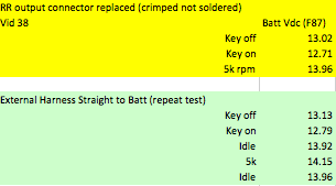
38 - RRConnReplaced13-9VDC from dcarver220b on Vimeo.
39 - ExtHarnessIsBest from dcarver220b on Vimeo.
40 - OemHarnessSolderedRRTerminals from dcarver220b on Vimeo.
45 - EasternBeaverHarness from dcarver220b on Vimeo.
Numbers...
Thoughts
Posted 12 July 2012 - 01:07 PM
Did some troubleshooting last night and took video of testing results..
And here are those results in a table. Not sure what all this means yet, as in what values are acceptable or not..
(apologies for sending you off to the CandyButtAssociation site, but I can't get tables to post nicely here..)
Some observations:
Has anyone else noticed greater output at idle rather than 5k rpm?
7/13/12 - Troubleshooting flow chart
4strokes.com/tech/fault_find.pdf
07-13-12 How a charging circuit works
http://www.electrosport.com/technical-resources/technical-articles/how-m...
The Basics of a Motorcycle Charging System On almost every motorcycle you will find a battery, used for providing power for starting the bike and for buffering an amount of electric energy. The battery itself is charged by a generator driven by the engine, and as long as the engine is running there will be a current flowing through the battery. The no load voltage of a fully charged battery is about 13 Vdc. For charging it the charging-system should provide a voltage of about 14.4 Vdc and this should be a constant voltage at all engine-speeds.
The generator itself is located in or on the engine, and on most bikes there is a separate regulator-rectifier unit located somewhere on the frame. The reason for this is that almost all motorcycles are equipped with a three-phase AC (Alternating Current) generator, while the electrical system on the bike is a DC (Direct Current) system. The rectifier part inside the regulator-rectifier takes care of converting the AC-current to the DC-current the battery needs. The three-phase AC generator is used so often because it is much more efficient and reliable than a DC-generator. It can produce power for charging the battery even with the engine idling. The regulator part of the regulator-rectifier is used to regulate the output-voltage (to the battery) to the 14.4 Vdc that is needed.
The Permanent Magnet Generator System A generator on a bike is producing this electrical power because it has a copper wire winding on the stator (the static part of the generator) that is located inside a varying magnetic field. The simplest generator uses a flywheel that runs on the crankshaft with a couple of magnets inside it. We call this flywheel with its built-in magnets the rotor.
FIGURE 1: PERMANENT MAGNET GENERATOR
The magnets themselves have north and south-poles and the flywheel is rotating around the stator. The stator is a metal core with a lot of metal poles that have windings of copper-wire on them. Because the flywheel is rotating and there are north and south-poles inside it, the windings of the stator are exposed to first a north-pole, then a south-pole, then a north-pole again etc. This is the varying magnetic field that is needed to let the winding itself produce AC-current. The windings themselves are connected in a star (one winding has two ends and the three ends of the three different windings are connected together) so the stator has only three output wires emerging from it.
This generator-setup we call a permanent magnet generator. This is because the flywheel contains magnets that are magnetic all the time. The output of a certain stator is depending on the engine-speed (the higher the speed of the magnetic-field variation, the higher the stator-output), and the force of the magnetic field (which is constant) Basically the stator produces a certain output at a certain rpm.
Then the AC-current is led through the rectifier inside the regulator-rectifier-unit. The rectifier converts the three AC-phases to a single 14.4 Vdc output, a ground and a positive. Because the stator is producing power according to the engine-speed the stator-output is too high all the time. This would mean the output voltage of the regulator-rectifier would be way over 14.4 Vdc all the time, which would result in an overcharged battery and blowing electrical components on the bike that were meant to run on a voltage between 12 and 15 Vdc.
Luckily there is also a regulator-part inside a regulator-rectifier. The regulator looks at the DC-voltage across the battery-terminals and short-circuits a certain amount of power that is produced by the stator to ground. This is regulated constantly, so the output-voltage of the regulator-rectifier (which ideallyis the same as the voltage across the battery-terminals) stays at 14.4 Vdc all the time.The permanent magnet generator-setup is not very efficient, but it is very simple and quite reliable. This explains why it is the most commonly used system on motorcycles.One of the problems with these systems is the short-circuiting of the excess power itself. This is done by the regulator-rectifier and this part has to dissipate the power that it shorts to ground, meaning it will get very hot. This is mostly because of the regulator and partly by the rectifier-diodes themselves that get hot just because of the current flowing through it. The regulator-rectifier internals need to be built so that the heat is transferred efficiently from the electronical components themselves to the housing of the unit, mostly equipped with cooling-fins. This is the most important bit in designing a regulator-rectifier for use in a permanent-magnet generator-setup.
The regulator-part of the regulator-rectifier needs to measure the DC-voltage somewhere in the system. On the cheapest built units (quite a lot of OEM ones) this is done not by measuring the DC-voltage in the DC-system, but by looking at the AC-voltage in between one stator-phase and the ground, and sometimes the excess power is shorted to ground from just one or two input-åAC phases instead of all three phases that are regulated. The better built units measure the output-voltage of the unit itself and regulate the input AC accordingly by shorting more or less power to ground, an equal amount off all three phases.
FIGURE 2: PERMANENT MAGNET GENERATOR FIGURE 2: PERMANENT MAGNET GENERATOR
Some units use an extra input wire (FIGURE 2) to measure the DC-voltage.This wire normally is connected up trough the ignition-switch and not straight to the battery.So there is only a voltage on this lead if the ignition is turned on. This is done to make up for a voltage-drop that can occur because of a bad-connection in the leads from the regulator-rectifier output to the battery-terminals. These leads carry a high current and any bad connection here will result in a lower voltage over the battery-terminals. The extra lead carries a much lower current and the result of this setup is that the output-voltage of the regulator-rectifier will be higher, the same DC-voltage as the voltage-drop in the high current leads plus 14.4 Vdc. It has the advantage that the battery will charge, in spite of a bad connection, but has the disadvantage that the high-current leads can eventually burn out because of this, without the owner even noticing beforehand that there is a problem in the circuit.
One thing to keep in mind is that the output-power provided by the stator-winding is delivered in between the phases. The ground in the charging system is the negative output from the rectifier. The AC-part of the three phase system is floating from ground. This means that testing of the AC-output needs to be done IN BETWEEN two of the three phases, and not from one phase to ground.
2012-07-15
placeholder
2012-07-16 Eastern Beaver
Jim at Eastern Beaver has RR wiring kits!
Hi Jim,
I know you're busy, probably getting ready for a big ride, so I'll keep this short and sweet.
My 2006 FJR1300 has large voltage drops, e.g. current path(s) from RR output to battery. Confirmed by bypassing oem wiring and going directly from RR out to batt, using a homemade wiring loom. The RR is FH020AA which I understand to be an updated FH012AA.
I'm interested in your kit FH012/011/010/009 Complete Kits Part A - the Battery Connection:
The battery is located in upper front right nose cowling. I'll measure distance when I get home tonight.
Questions -
1. Will the FH012 connector fit the FH022AA RR?
2. Would you be able to build a kit with the fuse location at a distance I specify (want it near the battery, not buried by RR (low back, middle), e.g. want it easy to get at and out of the harsh environment.
3. If I send a pix of the oem connector (leading to main fuse) and you have one, could we build that into the harness?
3. If yes would you be able to ship before your August holiday?
Thank you, by the way, I've ordered stuff from you in the past, it works great, quality even better.
Thanks Jim,
Don Carver
2012-07-16 FjrForum Comments
From here
Posted 16 July 2012 - 09:11 PM
But seriously, Don...something definitely whacky goin' on in the electrical system to have such wildly different readings between the OEM harness and a straight shot from the RR to the battery.
Keep up the detective work. You're gettin' closer
I'm sure Alan or Fred had you check, but have you done a voltage drop test between the RR and battery? Maybe I'm calling it the wrong thing. I'm not saying to measure volts at each spot to see the difference. You put one lead on the RR wire at the RR and the other on the battery. Do this on both the pos. and neg, side. With the meter set on volts you should see 0 ideally, less than 1 volt is OK. This test is checking the condition of the wiring between the 2 points. If the wiring is poor, or too small then voltage will go threw the gage that you have hooked up in parallel. If all is OK no volts or very little will go threw the gage.
RR, you're on the right track. I've done voltage drop tests and resistance checks across both legs of the charging circuit. Resistance says 0, voltage drop indicates not. Just like Prof IonBeam said. Trust the Prof, trust me.


 "
"
Tonight I tested the ground leg by removing it from the battery and placing it on the frame in various locations - near the steering head and way back on the stupid swing arm. Great output - note the 'external harness or EH, in place).
I then removed wiring from all but one connector near the main fuse to check crimps, corrosion, etc. All looked great. Even tried to connect RR + to wiring near main fuse but had no way to connect with the large lug up there.. So scrap that test.
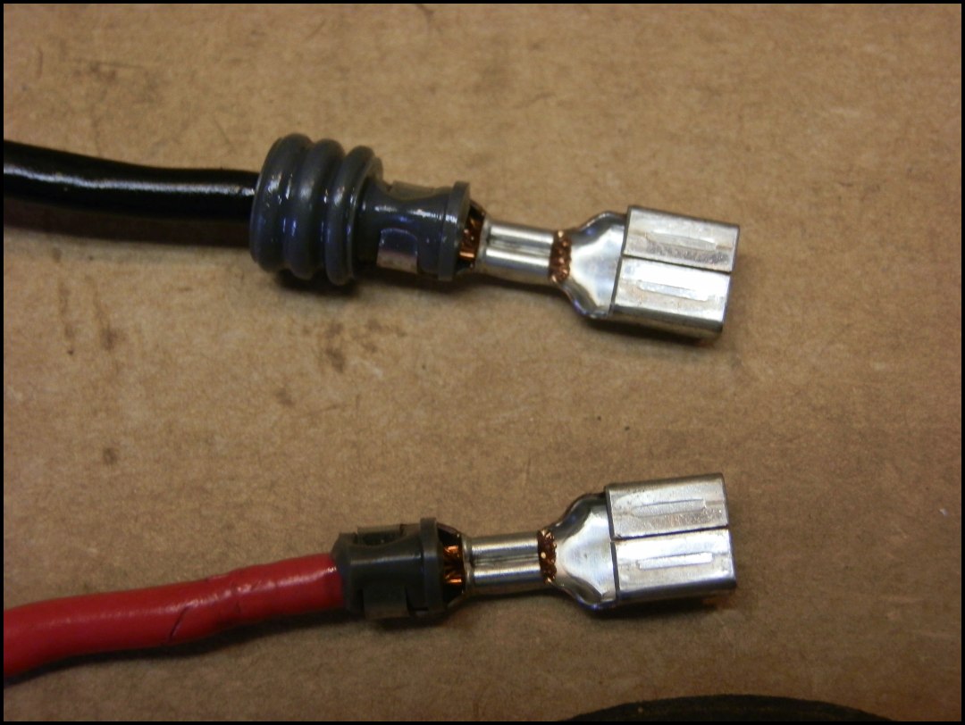
Maybe the connector at RR output? Cut if off, crimped two female connectors (no solder, but good clean crimp), and yes, the VDC a battery improved, very much so... but not to same level as direct connection to battery from RR.
This, me thinks, is the big clue. Any slight resistance... will cause voltage drop. Even the difference between a freshly crimped connector and one soldered. The OEM has several crimped connectors along the path. When I see guys on Ebay and Jim at Eastern Beaver selling kits that go from RR direct to battery with inline fuse, with kits for numerous bikes, that tells me something.
At this point, I say screw it. I'm done trying to find the smoking gun. I'll post up another thread asking if anyone has spider harness and check local dealer, just to see if my theory that somewhere, there is another junction, not listed in FSM schematic, just like my 61 Chevy did to me.. Bastids..
Another thought is that many times new, fresh, perfect as can be production looms decay with time. Marginally built to save $$, soon enough the decay and issues arise. Just like the FI harness on a 6-cyl Jeep Cherokee I once owned. Not a single root cause, but multiples leading to the aggregate.
Other thoughts, observations..
What a wonderful learning experience this has been! I actually understand how permanent magnet load shedding alternators work.
I learned the wiring harness for a gen 2 FJR,and every page of FSM wiring schematic.
I learned Professor Ionbeam is always right..
I learned that 14.2 volts on a gen 2 FJR is possible at the battery, 14.1 with HID's, fans on, hi beams on is possible.
I learned that my stock regulator has higher Vdc output, runs cooler at idle and hotter than upgraded RR at 5k rpm and heavy load.
Conversely, the upgraded RR runs hotter across all loads and rpms, and has marginally better current output.
I learned the upgrade RR uses Mosfets, not diodes like the OEM RR, and will shutdown rather than burn out if design parameters are exceeded.
I learned the OEM FH012AA has been updated with a FH020AA.
I learned taking videos of the testing process is invaluable - reviewing the videos later proves testing technique and discerned values.
I learned I can get absolutely KrZy with diagnosing problems.
Questions I still have -
What does it mean when Professor IonBeam says "Given a bike with it's history", and KaitsDad says "You're now my favorite FJR problem child.
2012-07-16 comments
Posted 17 July 2012 - 10:41 AM
The SMOKING GUN?

Reviewing videos, one of the tests I ran last night was to chop the existing RR output connector off, crimp on some female terminals that were a bit too small for the wire size but kinda made it work anyway...
Results -
The crimped not soldered OEM harness now delivered 13.96 vdc at the battery at 5k rpm - although it take a bit to get there.
The external harness, soldered, and larger gage wire, delivered 14.15 almost immediately at 5k rpm.
Replacing the RR output connector not as good as using the external harness, directly connected, but still a significant improvement and food for thought for those of you running a tad low? KaitsDad?
Here's a short video of the replaced connector test.
As compared to direct connect via external harness.
All troubleshooting videos found here..
2012-07-17 Comments
Posted on fjrforum
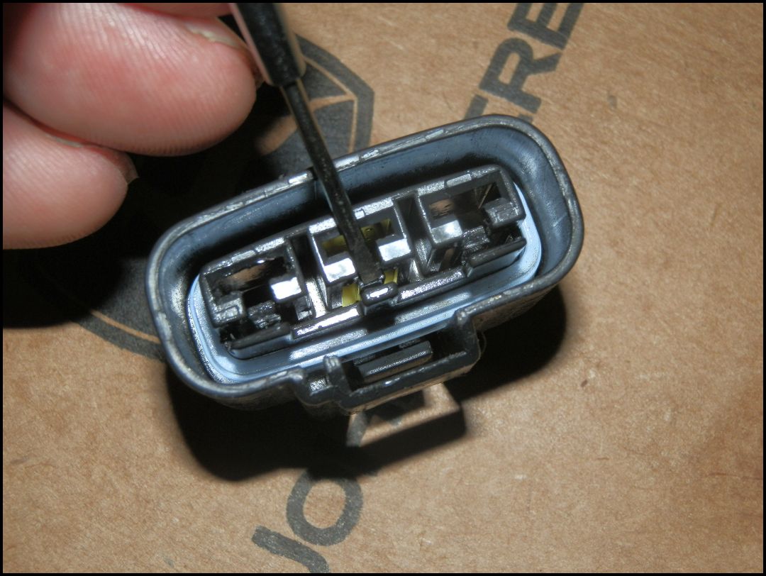
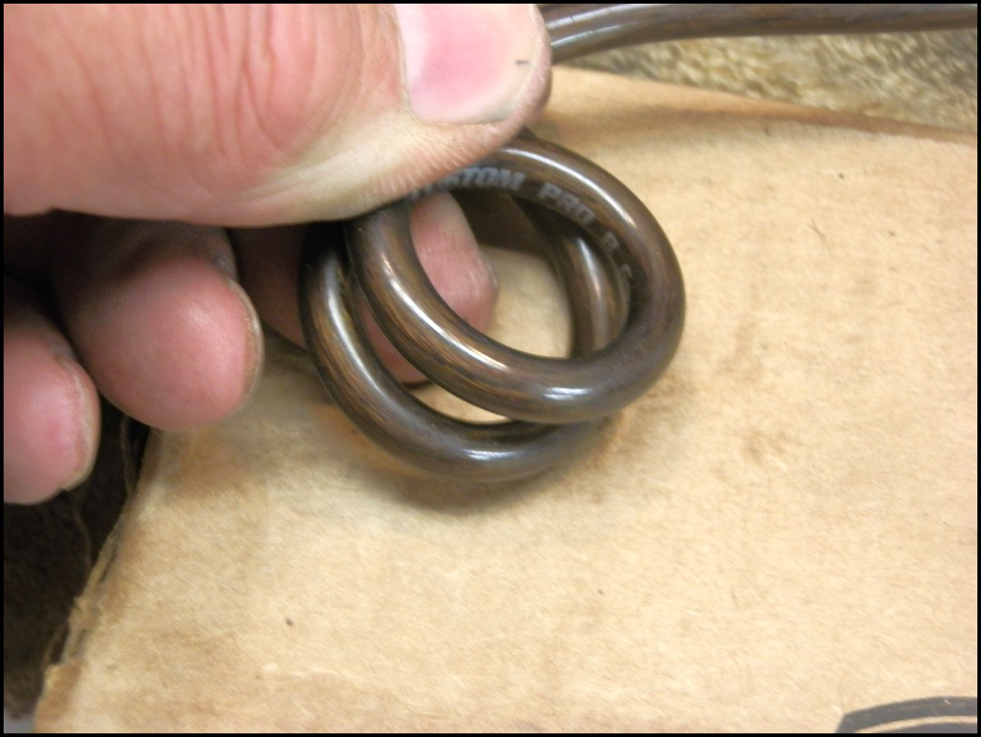
This pix - hmm, some plating degradation and minimal surface area contact point?
Walked away :) Is it really crashing if you don't fall down?--
2012-07-18
Stuff to do
2012-07-18 FjrForum Posting
Posted 18 July 2012 - 09:18 PM
7/18/2012
Last update, I had cut the OEM connector RR output connector off and crimped undersized female lugs onto the wire with improved results - almost up to par with external harness running direct from RR output to battery.
Removed the crimped connectors, re-crimped then soldered new ones on. Not much difference in VDC at battery, so the mechanical crimp was doing well. The delta remains 0.2 VDC less when running through the OEM harness vs straight to battery with external harness.
I videoed voltage drops on both hot and negative legs, but they didn't turn out. Will repeat later - bottom line is external harness was just at 0.1 vdc drop from battery hot RR hot, OEM harness was running a solid .2 to .28 VDC drop.
This was confirmed by the VDC delta as measured across battery then RR output - same amount of difference. I wish the video had turned out. Oh well.
Off to order a wiring harness from Jim at Eastern Beaver!
EDIT
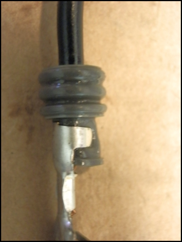
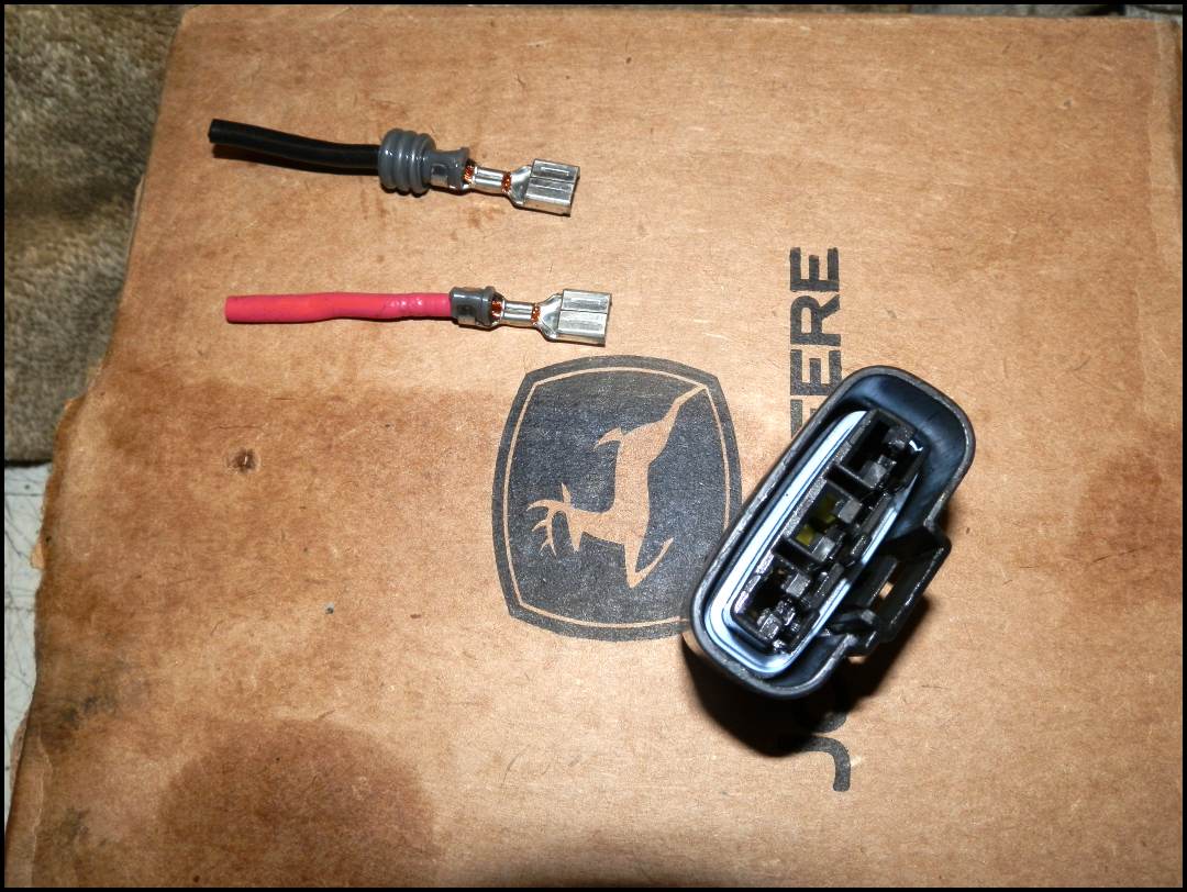
OEM RR connectors
Interesting that rubber boot is crimped..
Once the yellow barrier is removed (small screwdriver, it's not captive) yah gots to press here to release the lug.
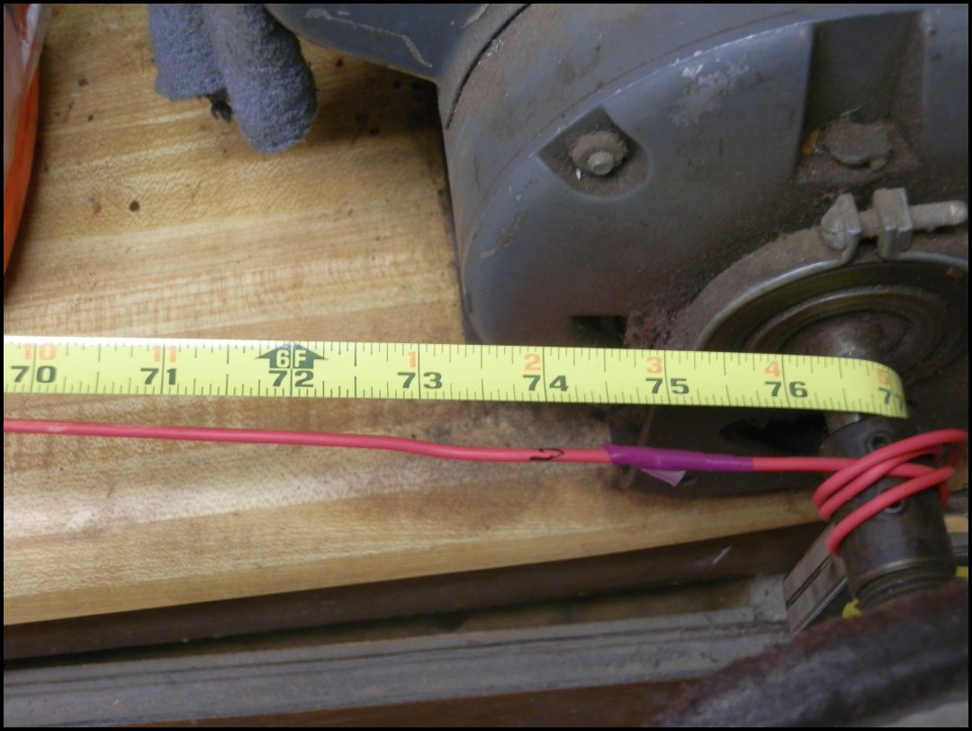
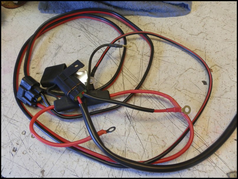
On the bench
My external harness will be this long.
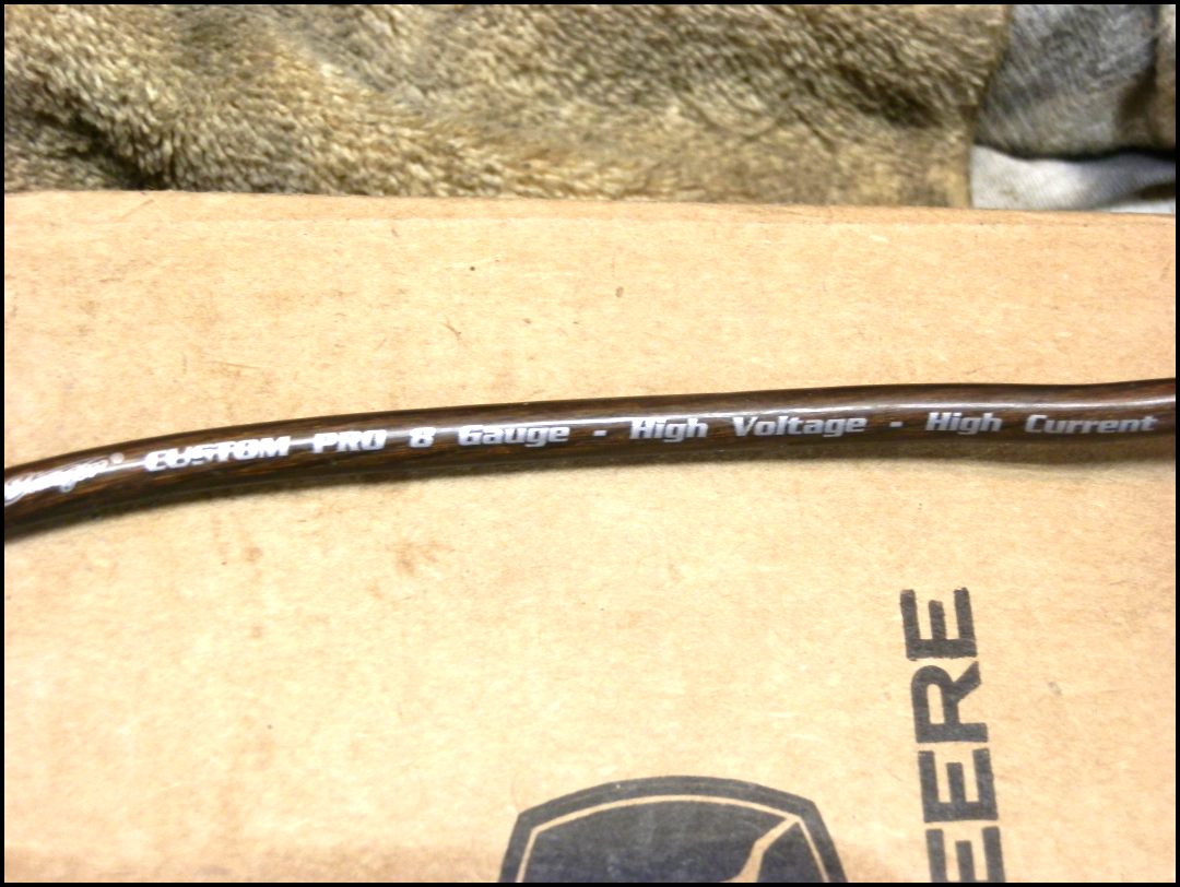
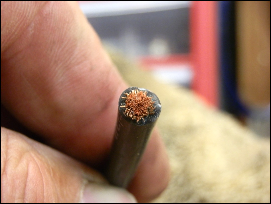
Wonder if this kind of wire, stereo power amplifier would work well?
2012-07-20 FjrForum posting
Posted 20 July 2012 - 10:38 PM
If there is one thing learned, me thinks, is that not always is *one* issue the problem, rather multiple components aggregating.
I think I've checked, cleaned, conditioned pretty much every connector on KrZy8Eh now -
Replaced the OEM connector going to main fuse..
Here is typical stuff I've seen at various connectors... this one Brodies ignition relay..
And YES, I did get into the ABS power connector... just could not resist.
Long of Short?
Video to follow...
Work done 7/20/2012
And video..
44 - I'm Done from dcarver220b on Vimeo.
This post has been edited by dcarver: 21 July 2012 - 11:19 AM
2012-07-30 Email to Jack at roadstercycle.com
Hi Jack,
I'm interested in your 'Super Harness', but with some mods and am wondering if you can build one for me, and if so, how much?
I need:
http://www.roadstercycle.com/
This is for a 2006 Yamaha FJR1300. I've done extensive testing, https://candybuttorg.ipage.com/cba/node/252, and even ordered an Eastern Beaver (EB) harness for it - but didn't get desired results. EB uses 12 gauge wire, you use 10. With the EB harness, I'm .2 to .3 volts less at the battery than when using 10 gauge. James K recently installed one of your 10 gauge harnesses and had great results, which is where I heard of you. The reason for the 50 amp breaker is that the RR is rated 50 amps, the OEM wiring uses a 50 amp breaker, and the 30 amp fuse / breaker is right at being maxed out - I'm measuring full current loads at 28 - 35 amps. The EB 30 amp fuse is too hot to touch at these loads, and the wiring is hot too. I'd rather run either a maxi fuse sized circuit breaker or similarly sized breaker.
I don't need any of the stator side stuff.
Any chance you can knock this one out before you leave on holiday?
Off to your website now to order some connectors...
Thanks Jack,
Don Carver
dcarver@calpoly.edu
805-458-2311
2012-08-09
Posted 09 August 2012 - 08:45 PM
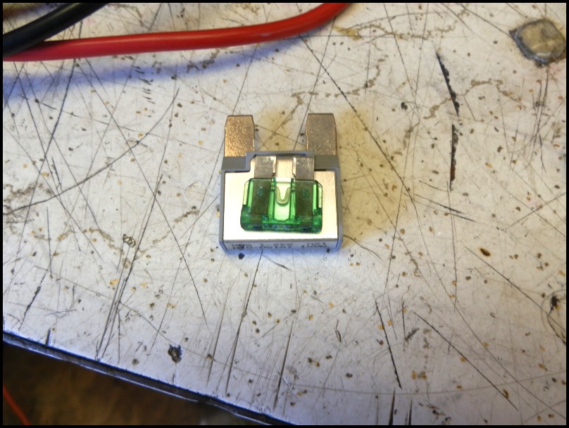
Regarding reversed terminals in MaxiFuse, this is normal, per Jack. Hal is right, designed to keep tension on terminals. The fuse was too tight of fit.. Really, it took pliers to remove fuse. The 50 amp CB inserted much more easily, probably a smaller blade width?
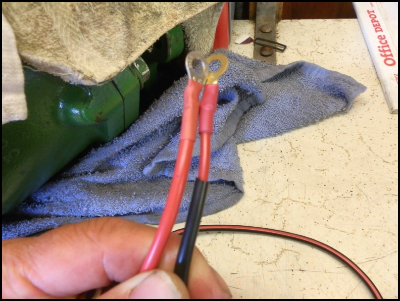
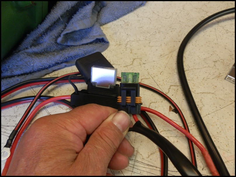
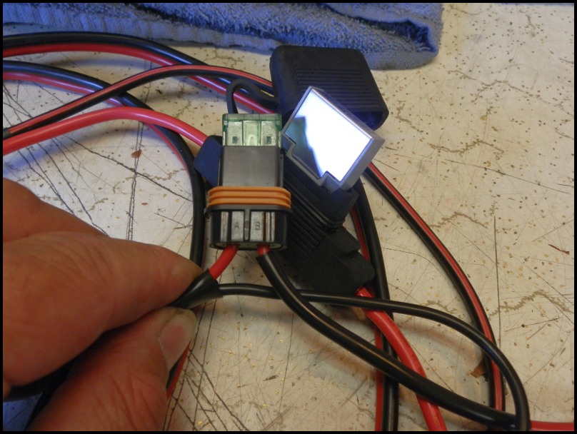
Here are some pix of EB and 'Jack' harness..
Hot in the shop
I think the pix say it all..
2013-06-11 All Still Good
Happy to say that well after a year later, all charging is A-OK, no degradation.