- Home
- Forums
- Ride Reports
- MotoBikes
- Restorations
- Wrenching
- 1963 BMW R69s
- 1969 BMW R60/2
- 1978 Yamaha 125
- 1979 KZ1300
- 1979 Kz1300 - Bob's Beauty
- 1981 CBX SuperSport
- 1981 Kz1300 Model A3 - Chocolatie
- 1984 Ford F250 XL
- 1987 ATK
- 1987 MowieMowie
- 1987 RotoTiller
- 1988 Honda Accord Lxi
- 1990 BMW RT100 - Barrie
- 1991 Harley Davidson FLHTCU
- 1992 Johnnie Deere
- 2000 YZ426
- 2002 Dodge Ram
- 2006 Carson RacerX Trailer
- 2006 Host Camper
- 2006 KrZy8
- 2007 Wabs
- 2012 KTM 690R
- 2013 Naomi - FJR 1300
- 2014-08-01 Air Compressor - Sears
- 2017 Kioti
- 2018 Toy Hauler
- 2020 Honda Fit
- 2021 Miscellaneous
- 2024 Log Splitter
- 2024 NeoDyne MC Lift
- 2050 test
- Lil Trlr
- Eats
- RIP
- PC Not
- Cages
- Test
- FJRF Best
- For Sale
Candy Butt Association
World's Wimpiest Riders
You are here
2023-03-27 Kz1300 Ignition Health Check

Forums:
2023-03-27 Kz1300 Ignition Health Check
Got to thinking about the 'popping' sound heard in exhaust, amplifed by the 6-1 DG exhaust header/muffler.
How long has it been since the ignition system was looked at?
Decades ago installed 'Martek' coils and silicone wires.
After doing a valve adjustment, placed all plugs on valve cover and spun the engine. #6 looked weak. Installed a new plug and it was
better, but not snappy blue hot either.
And I'm pretty sure Ray just used existing parts during the rebuild process.
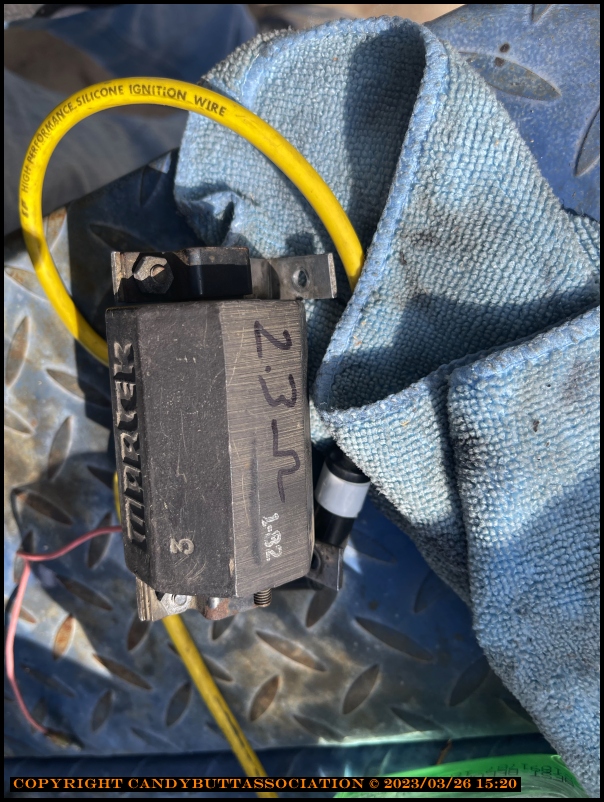
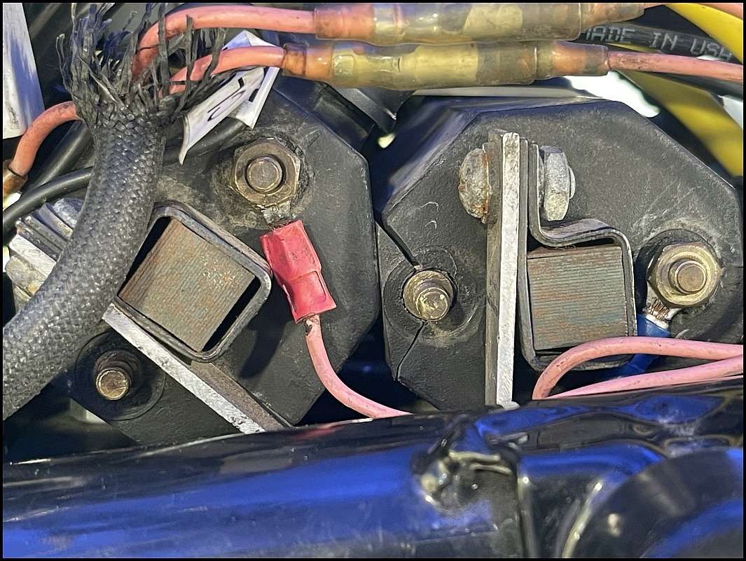
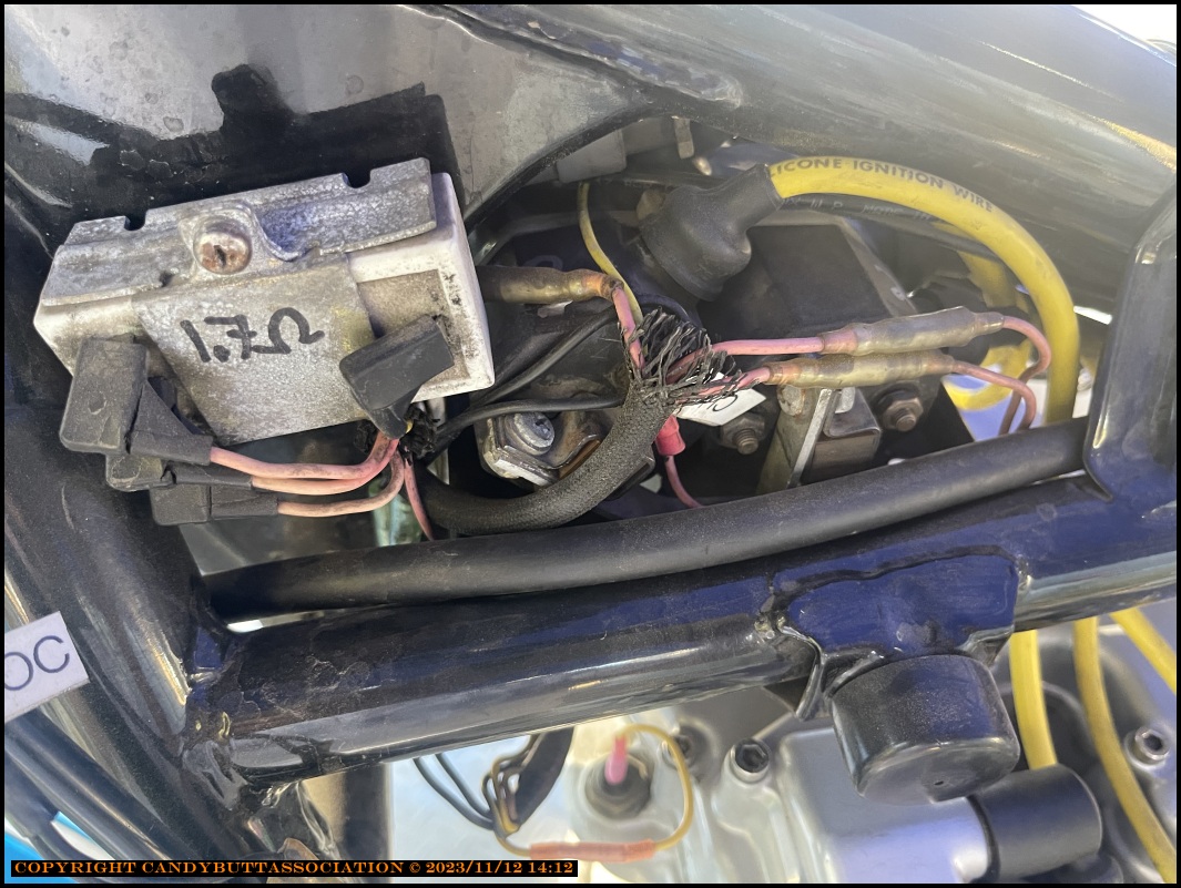
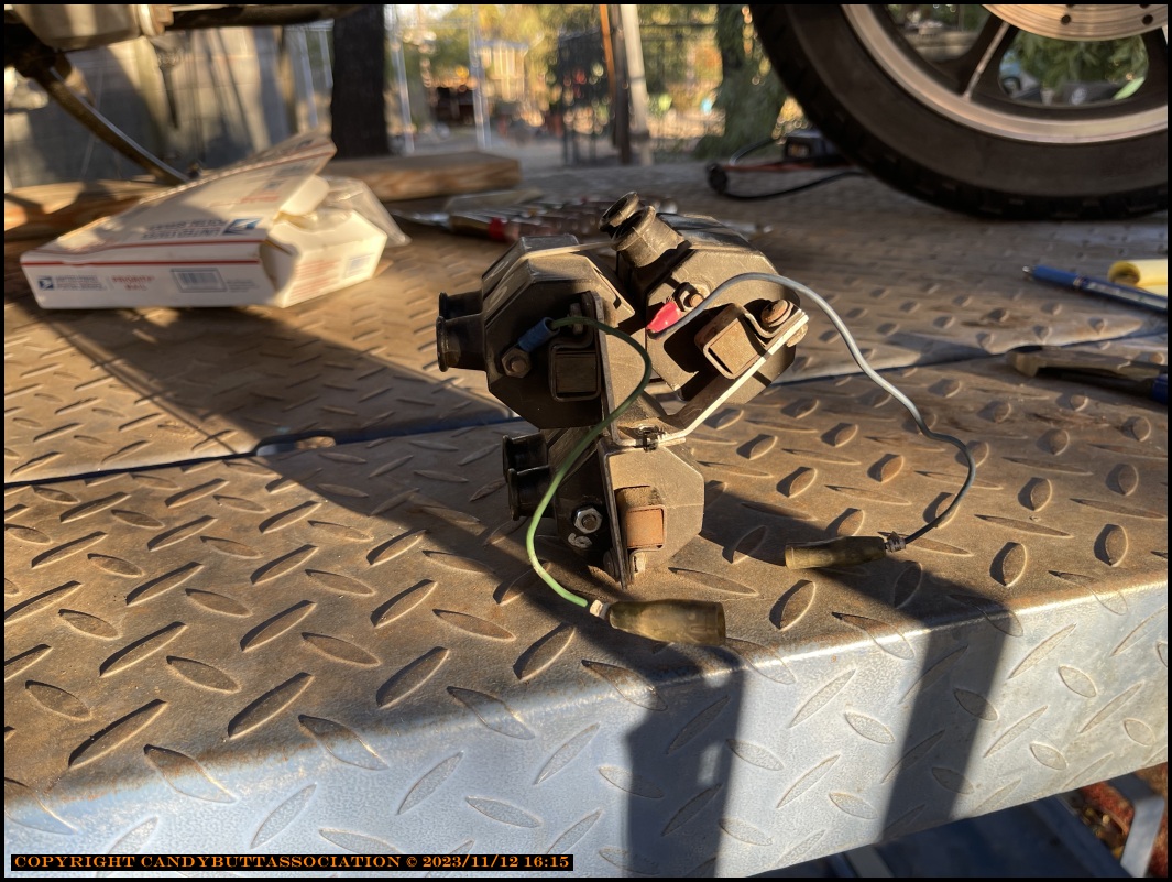
One of the 3 coils.
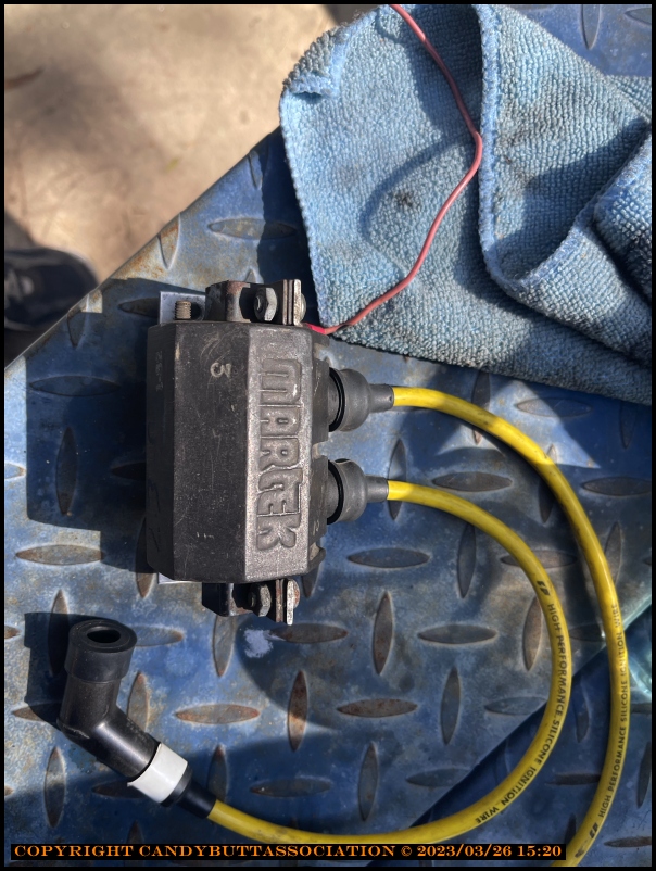
Across the terminals, 2.3 ohms.
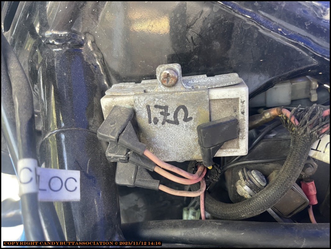
The ballast resistor measured 1.7 ohms across all three legs.
Not sure if the ballast resistor should be used with Martek coils.
Found this
Hello,I just got a set of martek coils off ebay,with the instruction sheet. For road racing and normal street use,{non CDI ignitions}use only terminals 1&3.Connect the 12 volt wire to
terminal 1,connect terminal 3 to points,or electronic ignition. Cover unused terminal 2 with anything to keep it from shorting to anything. Possibly a wire nut.
Found This which indicates a hi R (3.5 ohms) does not use ballast resistor.. My primary resistance is 2.3 ohms..
Brand new 12V CDI ignition coil to fit:
Kawasaki (K) Z 1300 A (1979-1982).
This is a high quality ignition coil, manufactured to replace any of the original coils on a Kawasaki Z1300 A1-A4 with original part numbers 21121-1019 or 21121-1017 or 21121-1018. It has 100mm mounting points and 2 spade connectors.
This coil is a high output 3.5 ohm (primary) coil so you may need to remove the resistor to run these coils, they will be an upgrade to the originals that are in place using the resistor. If you are having spark issues with your KZ / Z 1300 then upgrading your coils is almost essential.
If you're looking for a like for like replacement of the original coil 2 to 2.5 ohms primary, then please see our other listing
--------------
Looks like I need to determine if the Martek coils can produce hotter spark not using the ballast resistor and survive?
Theme by Danetsoft and Danang Probo Sayekti inspired by Maksimer
2023-03-29 Ignition Coil Primary side Current Calcs
Eliminate ballast resistor?
How much current allowable in primary windings of ignition coils?
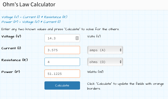
The Martek coils have 2.3 ohms resistance. Note I phooked up and used 2.4 ohms for below calcs.
No big deal.
So it's
I wonder what nominal is?
Coil only - about right, current-wise. See post below this one...
With ballast resistor - to little current = weak spark?
2023-03-29 Ignition Coil info from kz1300 FAQ page
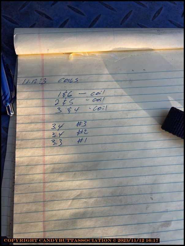
Q: Can anyone tell me which color wires feed which coils for the relevant cylinders?
A: #1 & 6 - Black, #3 & 4 - Blue, #2 & 5 - Green
Q: What are the symptoms of bad ignition coils and what are my options for changing out my original coils?
A: At some point in time, the original coils start getting cracks in them and go bad. I've seen this happen on these 1300's as early as only 7000 miles! It's not the best way to go, but you can bolt on the coils from the slightly newer Kawasaki's (80' - 85') with the removable leads and a primary resistance of 2.5 ohms in the same holes as the old ones.
These coils were used from 1982 to about 1989. The important thing to remember is that you remove the ballast resistor (if so equipped) so the total resistance to the CDI box is correct when installing the 2.5 ohm coils. Otherwise you’ll have problems with the primary resistance being too high. The original coils have a primary resistance of 1.5 ohms, and in conjunction with the 1.2 ohm ballast, the CDI sees 2.7+ ohms or a little more.
If the ballast goes bad and shorts out as it sometimes does with the original coils, the CDI would quickly burn up since the original coils are 1.5 ohms. Alternatively, if you use the ballast on the newer 2.5 ohm coils, the primary resistance will be 3.7+ ohms and that could damage the CDI also. The 2.5 ohm coils are a bolt on replacement for your old coils and as a bonus, they sport replaceable wires.
On the original coils, you couldn’t replace just the wires as the wires are made into the coils. You will have to make up some wires to power them up with because of the different connectors, but this is a simple task. To by pass the ballast, connect the one yellow wire which is the power in, to all 3 pink wires which is power out to each coil. You can solder them all together which is best or use whatever means you must to make the connection, as long as it's a good connection.
Whatever you do with the coils the total resistance at the end of the day must be same as what you started out with. If your total resistance (coils + ballast resistor) is 2.5 ohm then you should replace with 2.5 ohm coils and bypass the ballast resistor (which is approximately 1.7 Ohm and plenty WATTS). The reason this gives better spark is that you lose almost half your voltage in the ballast resistor! Replacing it with a 2.5 ohm coil means the coil get all the voltage your CDI is putting out and gives better spark. The CDI is expecting approximately 2.7 to 3.0 ohms so make sure it doesn't change.
: some calcs : 12v and 2.5ohm = 4.8 amps (Normal)
: 12v and 3.5ohm = 3.4 amps (weak spark)
: 12v and 1.5ohm = 8 amps = fried CDI unit, but good spark while it lasts ;-)
The last example is what you get when you use stock coils, but remove the ballast resistor or the resistor goes bad. It gives almost double the amps that the CDI is made for, and although it won't let the magic smoke out immediately it will soon.
The reason we can use 2.5 to 3.0 ohm coils safely, without knowing what a schematic for the inside of the CDI may look like is that we haven't really altered anything. If we study the maintenance section of our beloved Kawasaki service manual, we will discover that their is some variance listed, but the ballast resistor has a resistance of approximately 1.3 to 1.7 ohms. Stock coils have a primary resistance of approximately 1.3. to 1.7 ohms for a total of 2.6 to 3.4 ohms, but we'd like to be at the lower range, not the higher to get the best spark output.
There really is no risk because that CDI is still reacting to the same resistance it always has and doesn't really care whether it comes from a combination of resistors and coils or just one coil. I cannot say for certain what may happen with a 3+ ohm coil, but suffice it to say the higher you get the less spark output. Your other options are to buy aftermarket coils from Dyna, Nology coils, or some other high performance coil with the appropriate ohm rating. The Accel coils are much more costly at about $80 to $120 apiece; the Dyna’s about $70 each, Nology's about $75+ each (posted prices on the net as of Nov/2004). You can check the Accel installation page for more info at - http://accel.zn1300.com/
Update! Until 2005 I didn't have any problems with Accel coils, but read the Accel page for current info about Accel's ohm readings measuring too high! Not a good coil for us anymore in my opinion!
Q: What is the replacement Accel coil part numbers for the 1980 KZ1300B2?
A: Accel part #'s are 140403 (2 coils) & 140403S (Single coil). The same coil for all year model KZ1300, Z1300, ZN1300, ZG1300 and Voyager 1300's. All year 1300's use the same Accel coil. On the older bikes (83' KZ1300's or older) with the original 1.5 ohm coils and ballast resistor, you simply pull the ballast off, toss it in the trash and install the coils without a ballast. On the newer year model bikes that came with 2.5 ohm coils and without the ballast, you simply mount the coils and ride.
2023-03-29 Kawboy's Thoughts
From Kz1300.com, KawBoy (He's a fart smeller! :))
Okay, here we go again.
As per the Service Manual
Resistance in a series circuit (which is the primary circuit in the ignition) is the addition of the resistances of the components in the circuit so in this case. if we add the resistance of the ballast resistor to the resistance of the primary winding of the ignition coil we get 1.5 to 1.9 ohms + 1.2 to 1.9 ohms we get a range of 2.7 to 3.8 ohms total primary circuit resistance permissible to be within Service Spec.
Ohms Law states that Amperage = Voltage divided by Resistance so bearing in mind that the charging voltage of a running KZ1300 averages around 14.5 volts we can work out the amperage of the primary circuit.
14.5 volts / 2.7ohms = 5.37 amps
14.5 volts / 3.8 ohms = 3.81 amps
The service limits as spec'd in the Service Manual basically states that we can run up to 5.37 amps in the primary circuit and this will not damage the control switches in the circuit which are the Darlington transistors in the igniter.
So, as long as the resistance in the primary ignition circuit is maintained above 2.7 Ohms you should be fine. The only caution here from my point of view is that you would be running really tight to the maximum amperage that the Darlington's can handle and there would be no room for error.
I do remember that Trikbldr got in to this topic years ago and started explaining all the electronic theory regarding this primary circuit topic and he was adamant that "some additional resistor was required to dampen the (for the sake calling it something) reverberation of the voltage fluctuations in the primary circuit to protect the Darlington transistors. Trikebldr got really upset at members on this site referring to him as a blowhard and Trikebldr left us to our own demise and tootled off to his other favorite site American Voyagers Association since it was more in tune with his desires
2023-03-29 - Configure ballast Resistor in Parallel?
"The CDI is expecting approximately 2.7 to 3.0 ohms so make sure it doesn't change."
Email to my buds... Oh Lord
Email to my buds...
Oh Lord it’s hard to be humble…
2023-03-30 Good Ignition Coil Replacement Post on KZ1300.com
Found this really good post on KZ1300.com
2023-03-30 Ballast Schematic
From previous posts, folks have installed 3 discrete ballast resistors to replace OEM ballast.
Any good reason for this? Why not just one? If 8 cylinder V8's use just one, seems like a 6 cylinder motoBike could use just one?
In my world, I'd like to use OEM ballast resistor as it's tucked away nicely.. and don't have to buy yet something else..
..wire it in parallel, get resistance down to .57 ohms for a total primary circuit resistance of 2.9 ohms.
Advisable or not?
Thanks for the help guys, especially KB!
2023-03-31 Spark Plug Caps - Ign Coil Rewire
2023-03-31 Spark Plug Caps - Ign Coil Rewire
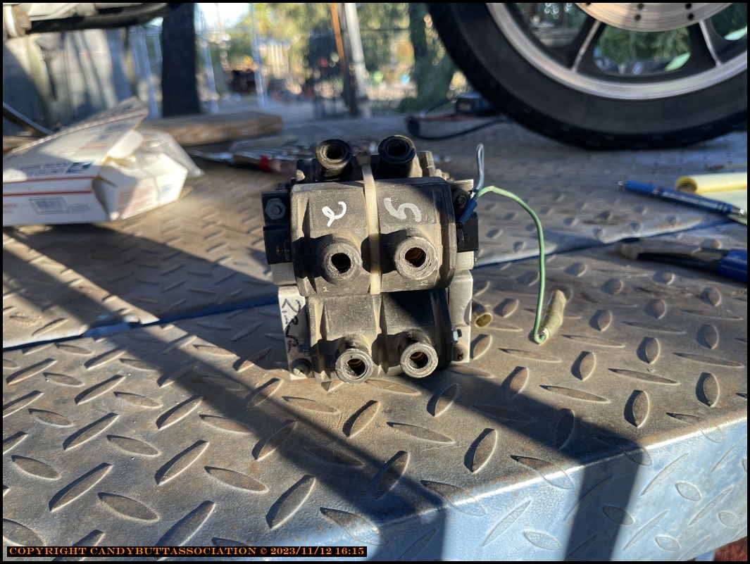
Got to thinking about the Martek coils. They have 3 terminals. Two on one side, one on the otherside. Is it possible the second terminal is another tap of the winding?
When I installed these coils, ~1980, I remember not fully understanding the instructions.
Sure enough the second terminal, the with a '1' scratched by it, is has a resistance of 1 ohm. Perfect! The ballast resistor is 1.7 Ohms. Add 1 Ohm from the coil, 2.7 Ohms total.
Just wht the doctor ordered!
Total resistance, ballast resistor + coil. All 3 read the same value.
To think, a mistake I made 40+ years ago, never questioned, causing weak spark all that time.
I'm ashamed, but more happy than shameful, to have found this!
Things are looking up!
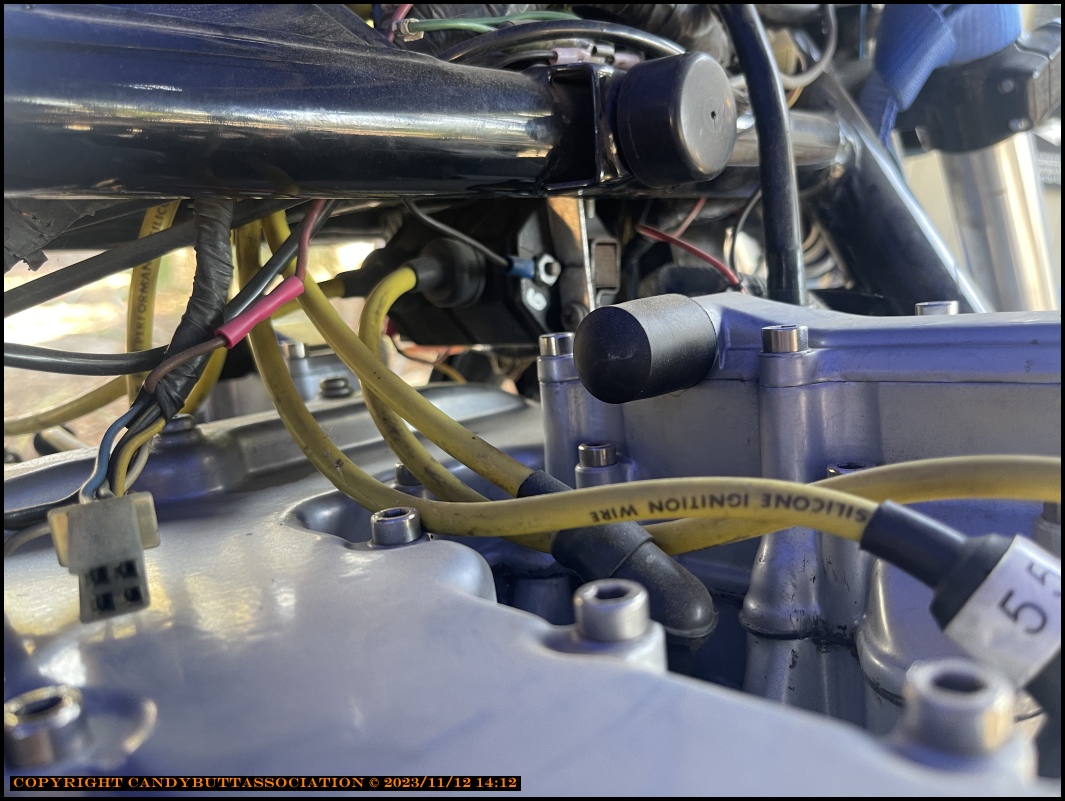
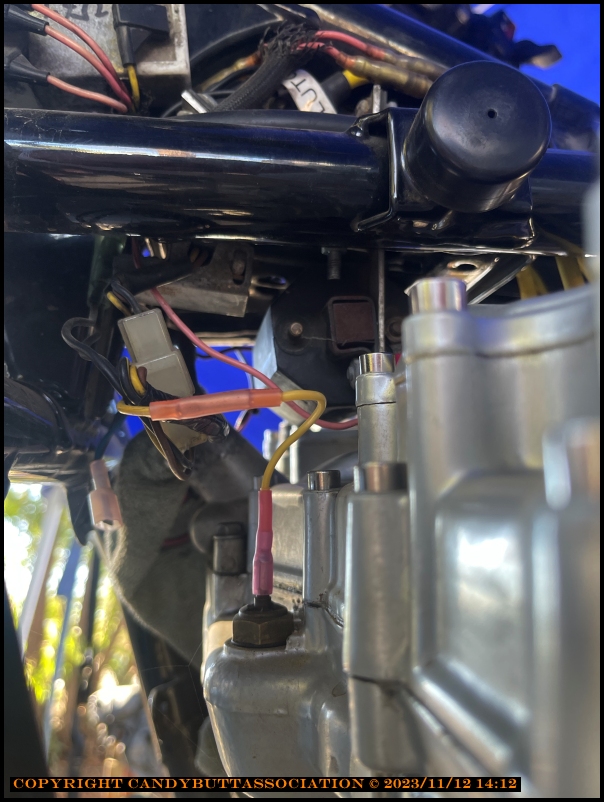
Checking high tension leads. First one pulled looks corroded. Not good.
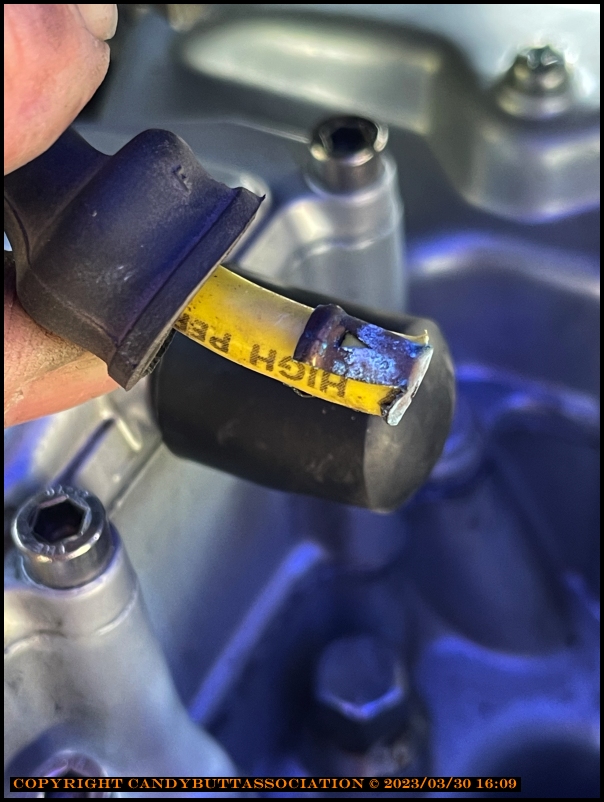
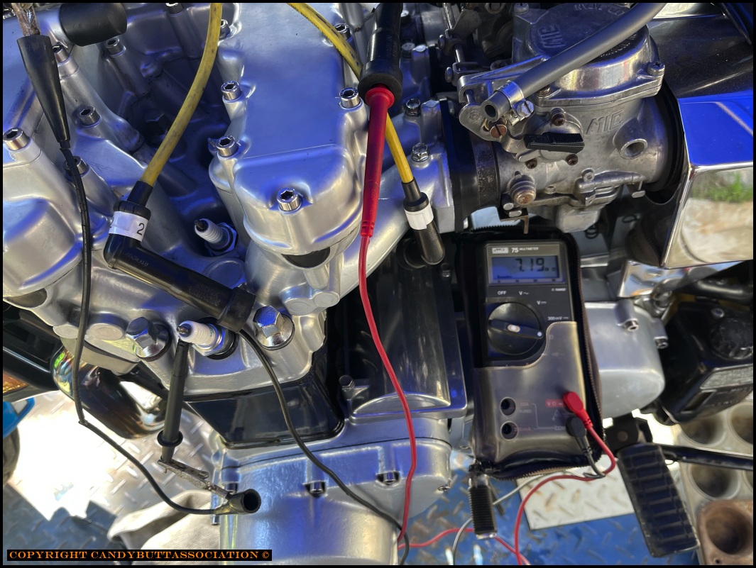
Assuming a 5k Ohm cap resistor, a reading of 7.2 MegOhms is not good either.
The end caps are not the same length as 'inner' caps. End caps are shorter. This is an 'inner' cap.
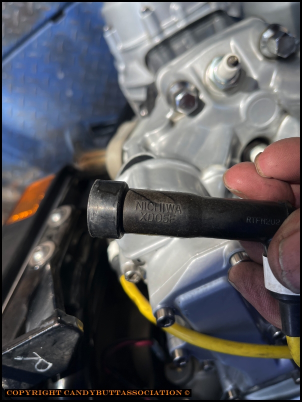
Pix for Mfr and part number.
End cap part number, e.g. cylinder 1 and 6.
Notes
Happiness was short live however..
She won't start now. Cranks, but no fire. Checked for spark, yep, it's got spark.
...and I've been having intermittent starter motor problems.. probably, hopefully the control switch? It hits, then, I'm therozing, opens, and the starter quits turning.
To be sure, changed the 2011 battery with a known good battery, same symptoms.
..and the one plug I pulled was bone-dry. Opened a float bowl drain, and fuel came out.
By then it's cold, dark, and I'm defeated.
2023-03-31 She Runs Again!
She Runs Again!
2023-03-31 Broken Coil, Spark Plug Tester, Fix NO SPARK
Spark plug tester on Mowie-Mowie
2023-03-31 Broken Coil, Spark Plug Tester, Fix NO SPARK condition
The big idea to place primary resistance to desired 2.7 ohms failed miserably. Weak, almost non-existant spark.
Put coil primary wiring to 'As Found' condition, almost 4 ohms on primary, and spark returned. Glad I didn't damage the Darlington power transistors in the
IC Igniter
Position '3' is the 1 ohm winding. '1' is the higher resistance winding that works.
Starter motor relay re-work. Kinda loose wire in primary connector, cleaned all connectors, and leads going to starter motor/ground.
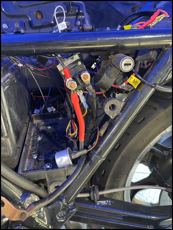
In the long run, didn't fix a thing. The starter kicks out after about 5 seconds. Releasing the starter button I can hear the relay kick out..
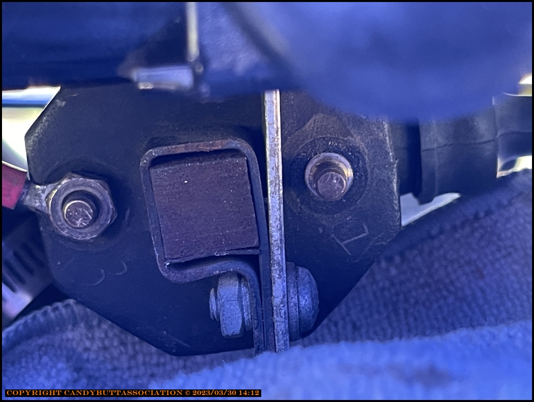
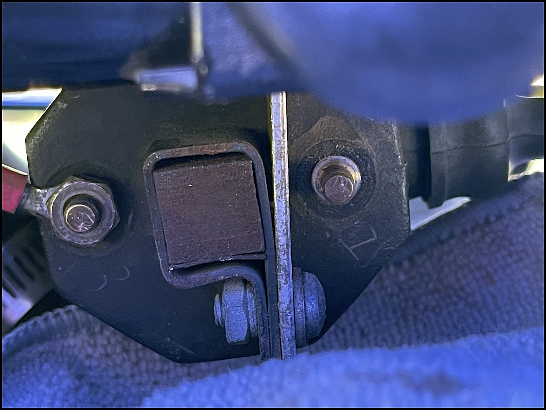
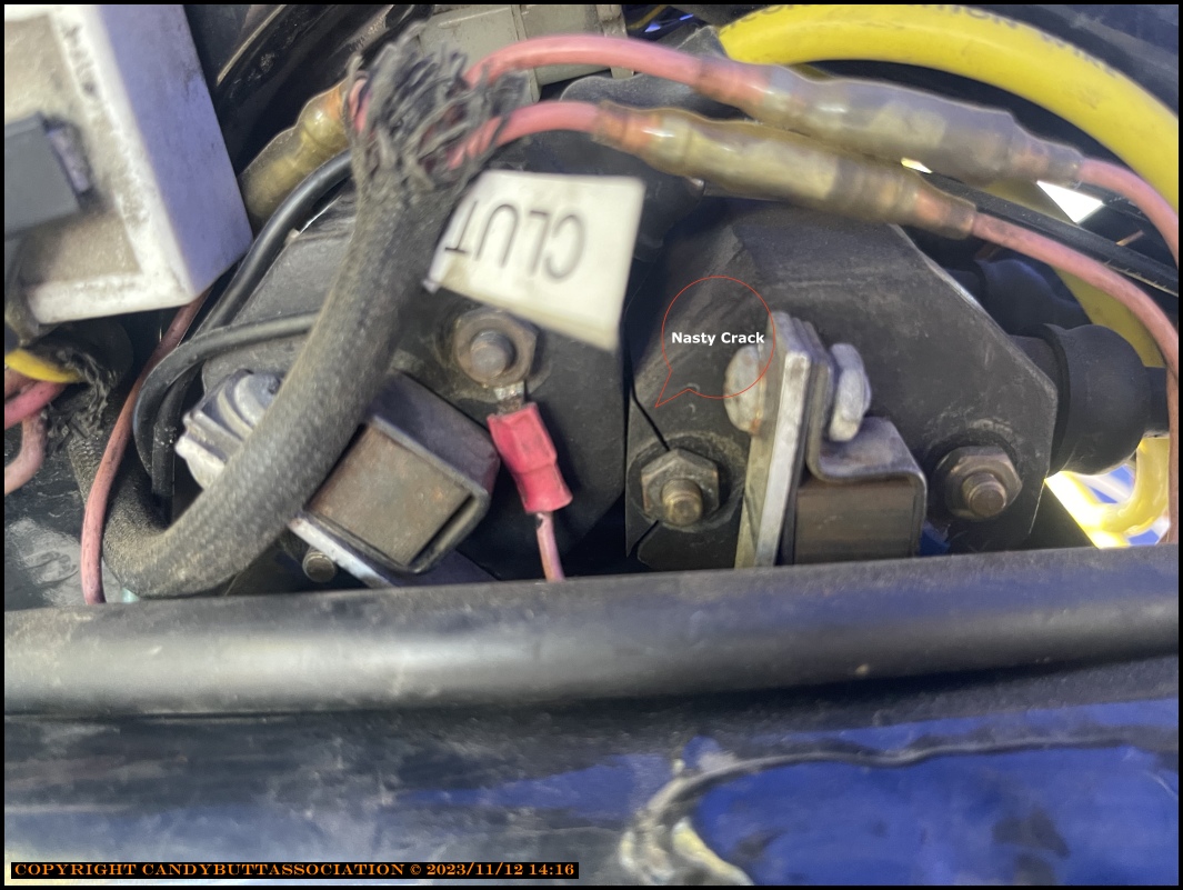
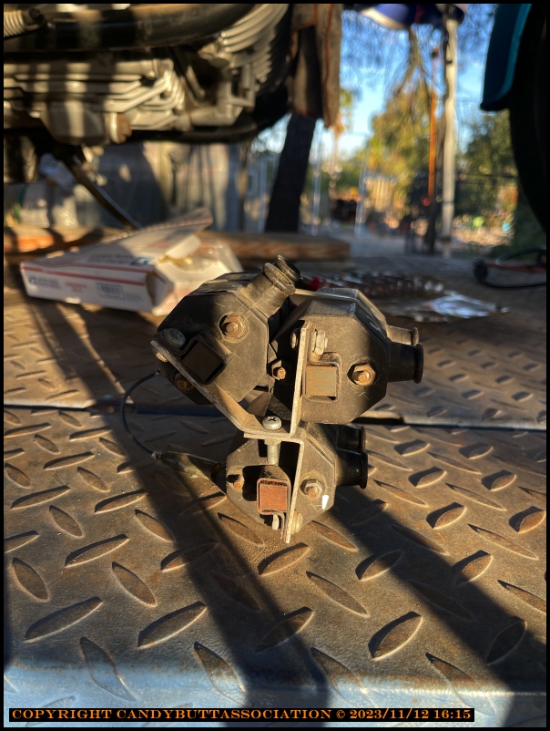
Split coil. I think it broke when the nut was tightened. Don't recall seeing the break earlier, and I was looking...
2024-04-19 Coil Replacements?
2024-04-19 Coil Location and Mounting, OEM?
One picture shows the diagram for the coils. Notice the standoffs? Hexagon shaped pieces that space the coils from the plate in the headstock.
Thread rods extend through the plate (4) upwards and (2) downwards to mount the three coils with nuts.
The coil side of the stand-offs are mounted with Phillips (star) screws I believe.
Red circled holes are for the coils that hang upside down, yellow are for the one coil mounted on top.
Hope this helps
2023-04-19 Coil Mounting Location Info
'll take a picture, as mine were just recently separated and post it to help.
One picture shows the diagram for the coils. Notice the standoffs? Hexagon shaped pieces that space the coils from the plate in the headstock.
Thread rods extend through the plate (4) upwards and (2) downwards to mount the three coils with nuts.
The coil side of the stand-offs are mounted with Phillips (star) screws I believe.
Red circled holes are for the coils that hang upside down, yellow are for the one coil mounted on top.
Hope this helps
2024-04-19 BP6ES spark plug upgrade
BP6ES iridum is BPR6EIX stock number 6637
2023-11-19 Kz1300 New Coils Install
edit
2023-11-19 Kz1300 New Coils Install
The temporary work gig at the nookie plant is over, about 1 week ago. Finding my civilian legs again, time to complete some projects.
How about we start with the bike already on the lift?
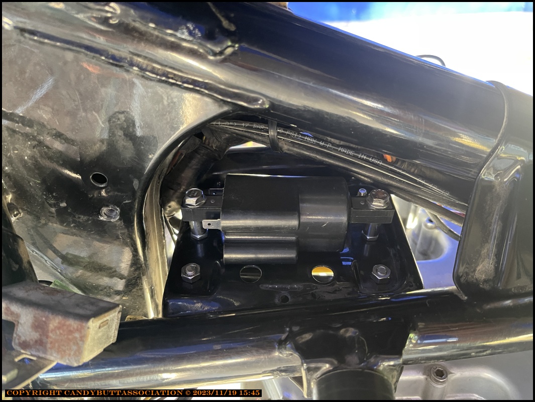
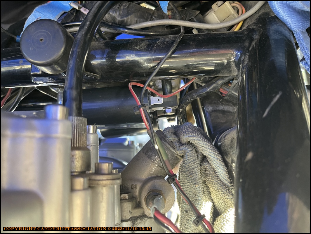
Pics of original install using Martek coils. I did this...1982 or so?
The Martek coil shape provided for easy install. Two on top, one on bottom.
I remember making these custom brackets in the Volumetrics machine shop, after hours.
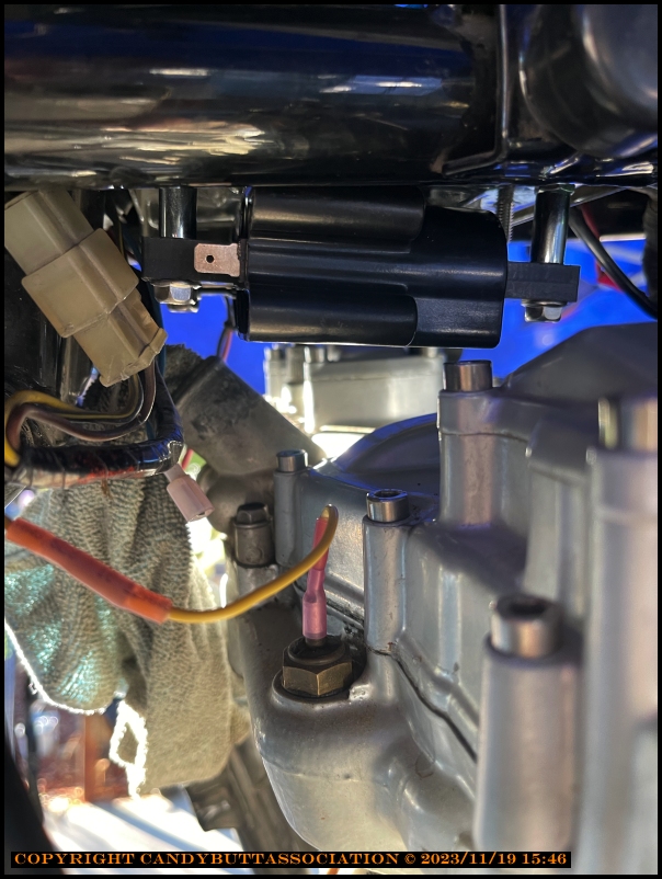
The reason for replacement.
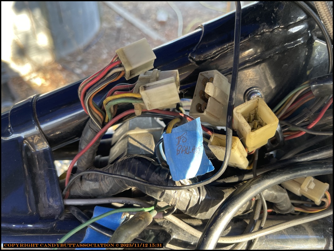
OEM ballast resistor. New coils don't require it.
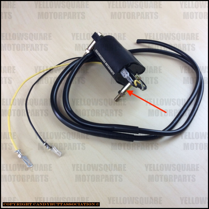
New stuff! 7mm copper center wire from Ton's, coils by YellowSquare.
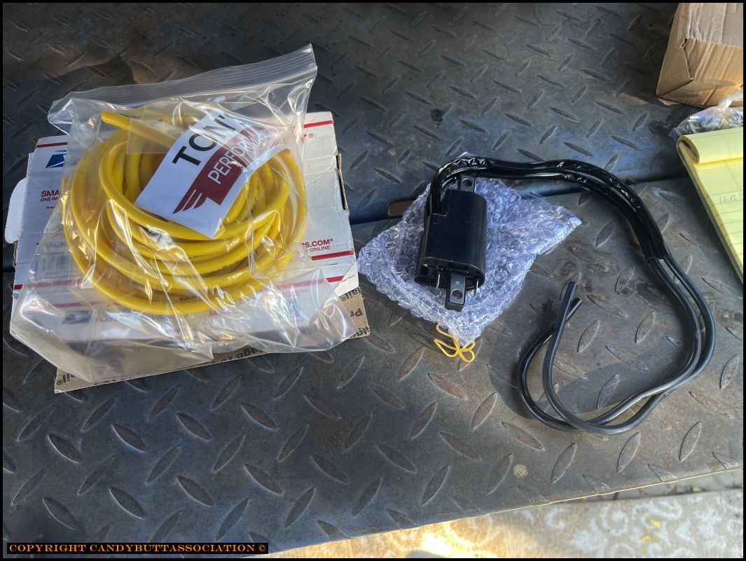
Ohms are 'in spec' to not overdrive Darlington transistors yet provide a hopefully HOT spark.
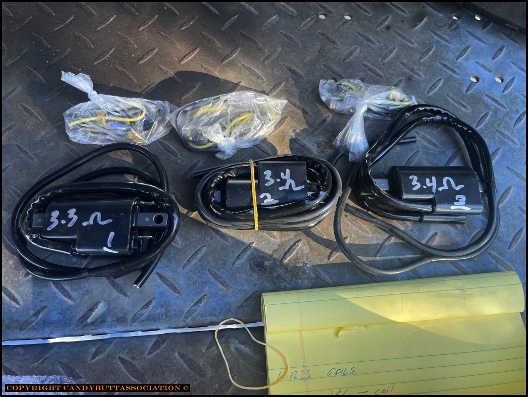
Won't be using these. Cheesy-Cheap.
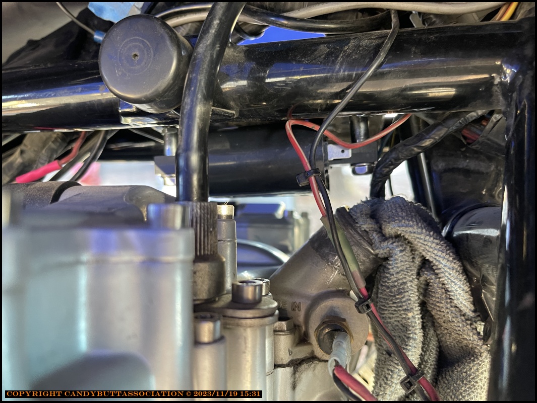
Tucked in tight.
Always good to label wiring.. especially on, uh, 'extended job durations'.
Off the bike now.
Can't believe these aluminum brackets lasted all those years.
.
Note to self. Coil and cylinders fired. Wasted spark syndrome!
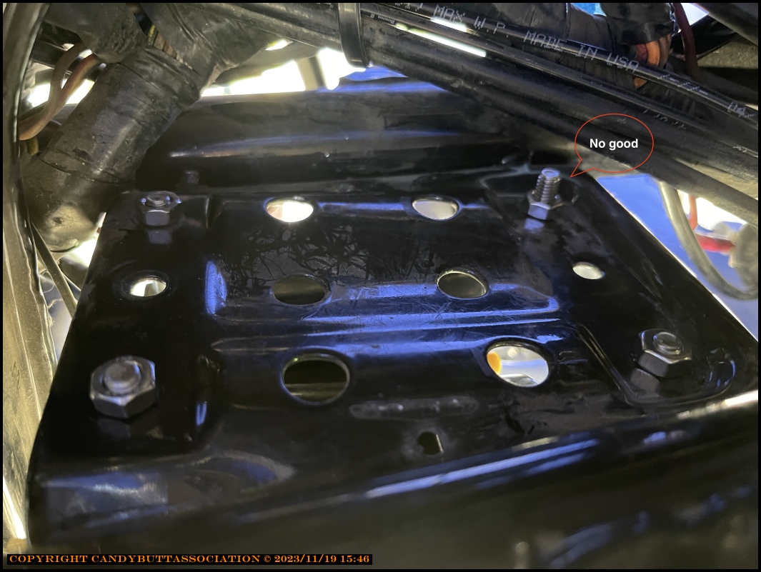
Replacement coils slighty smaller. They did not come with nice hardware indicated by arrow... rather a cheesy screw/nut and tiny tiny standoff. Useless.
Did a fitment test with new Ton's 7mm wire. Fits into coil perfectly (screws in).
Yes. All metric fasteners. Don't believe in mix n' matching metric and SAE.

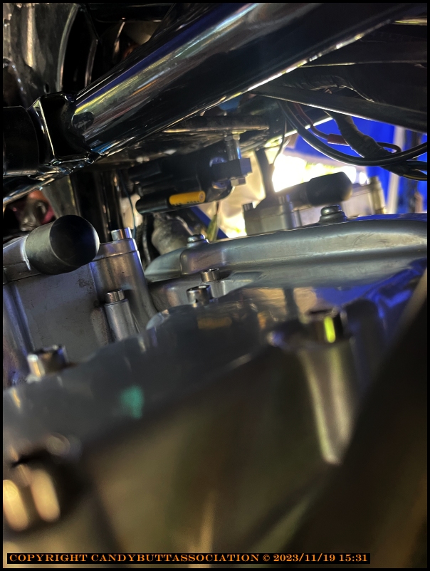
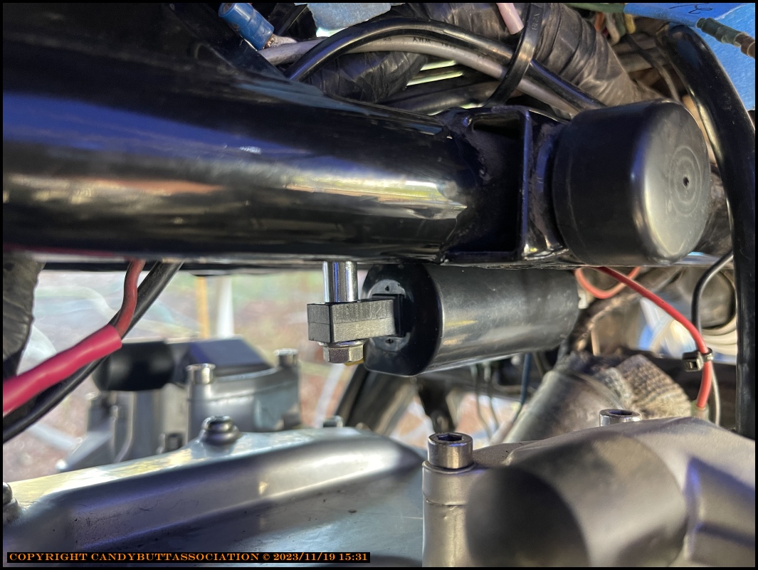
Looks ok. Almost good.
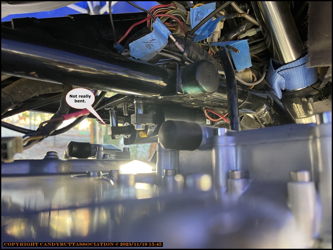
As caption says, not really bent. It's an illusion.
I need to bite the $$ bullet and buy a nice assortment of metric fasteners.

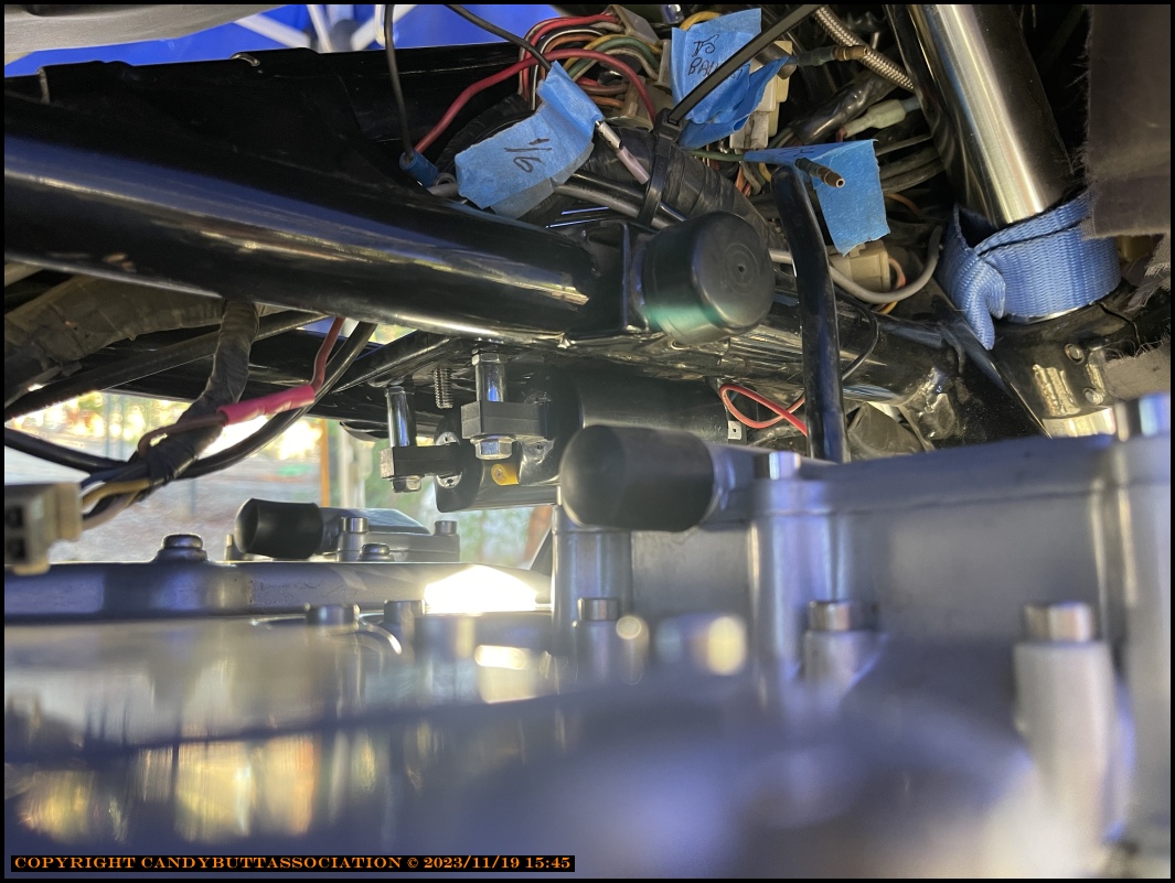
More room with new coils.
Mock up is good, so far.

Need to pick up more hardware.. One bolt too long, need more spacer sizes for optimal positioning.
... more later
2023-11-21 Coil Final Install Pics
2023-11-21 Final Pics of New Coil Installation
Almost done. Still have to connect primary windings to harnes...
All stainless hardware, metric.
Two under, one on top. Yes, they have to be removed to remove valve cover.
After all this hope they work better...
iPhone gives funny angles. The stand-off is actually straight.
Looking proper!
Eye candy!
Need some wire spacers still.
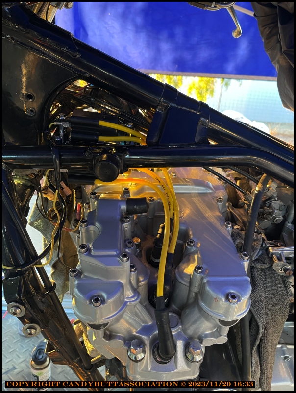
The End.

Now to wire the primaries.
2023-11-22 OhShit - Coil Install - Rad Hose
Well, I didn't plan on the rad hose not fitting under the coil...
2023-11-22 New coil spacing
Tucked the offending coil up closer to allow clearance for rad hose. Of course had to disassemble everything first. Getting kind of good at it though...
2023-11-23 Coil Wiring Questions
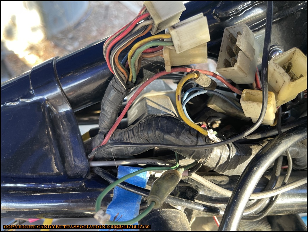
One should always think things through and not just 'know it'. Coil wiring for example. The three coils all had pink wires going to a ballast resistor on one end. The other end (yellow/red) tied back into the wiring harness.
Out comes the ballast resistor. Now time to wire up the new coils. Should be simple, right? Connect the + side of coil to appropriate igniter wire. Take - side of coil to ground.
Then got to thinking about it... Better look at a schematic.
The question now is, how does this circuit really work?
The diagram above shows the entire circuit.
Diagram above shows how I *think* the circuit works..
I think it's how it works..
Found more info...The diagram below shows the A1 ignition circuit. From FSM. Coil has been replaced, Resistor as well. So yes, coil + primary side needs to connect Yellow/Red from main harness (which goes to Igniter).
Final question is:
2023-11-24 KawBoy from kz1300.com replies
The Ballast Resistor drops the supplied voltage to the coils by inducing a resistance in the circuit
The 3 pink wires feed the reduced voltage after the ballast resistor to the positive terminals of the 3 ignition coils.
The Black, Green and Blue wires coming off of the negative terminals of the ignition coils are switched to ground through the Darlington transistors in the igniter.
If all you want to do is remove the ballast resistor, then take the 3 pink wires and connect them to the yellow/red wire and you're done. Bob's your Uncle, Mary's your Aunt. E'tutto Finito
Testing a circuit
First, let's talk about a voltage meter. A voltage meter measures the difference in voltage between the negative black lead and the positive red lead of the voltage meter. Most people will use a voltage meter to check for supplied voltage by hooking up the negative lead to the ground of the battery and then touching the positive lead to different parts of a circuit to see if they "have voltage". A simple test to see if you have a completed circuit but that's all.
In your diagram above, you have battery voltage supplying the Fuse, then the Main Switch, then the Ignition Switch, then the Engine Stop Switch then the Yellow / Red wire feeding the Ballast Resistor. In a perfect world, there would be no resistance in that part of the circuit so if you take your volt meter and attach the black lead to the negative battery terminal and attach the red lead to the yellow/red lead at the Ballast Resistor, you should see "Battery Voltage" ( If battery voltage was 12.8 volts, then the voltage at the ballast resistor should be 12.8 volts)
A better test would be to attach the negative lead to the positive terminal of the battery and then touch the red lead of the voltage meter to the yellow / red wire at the ballast resistor but now we need to understand what we are measuring and why do it this way. Back to the initial statement a voltage meter measures the difference in voltage between the negative black lead and the positive red lead of the voltage meter. So, in this test we are going to measure the difference in voltage between the red terminal of the battery and the yellow / red wire feeding the ballast resistor. In our perfect world, there would be no resistance so the voltage drop should be zero. So, do the test and you’re looking for zero voltage but what if the volt meter showed 1.8 volts? Difference in voltage means resistance is in that part of the circuit so how do we find the resistance that caused the voltage drop?
One way could be to go back to the first test and hook up the negative lead of the volt meter to the battery ground terminal and then take the red lead and check different parts of the circuit and go looking for Battery voltage at each and every point of the circuit. That test works in a circuit with no resistance in it and you could find the fault. A better test is to use the volt meter and test the voltage difference between the input side of a component and the output side of a component.
So, let’s say we want to find the 1.8 volt drop in your circuit. We have 9 components in your supplied voltage to the ballast resistor that could be a problem. What? I only see 4 items. Wrong. We have. The wire between the battery and the fuse. The Fuse. The wire between the fuse and the main switch. The main switch. The wire between the main switch and the ignition switch. The ignition switch. The wire between the ignition switch and the engine kill switch. The engine kill switch. And finally, the wire between the engine kill switch and the ballast resistor. Now you could use the first test and look for 12.8 volts at each and every point in the circuit but a better test would be to using your volt meter leads, go across each point in the circuit and look for zero volts, meaning no voltage drop.
The point I’m trying to get across is that looking for voltage drop in different parts of a circuit is easier to find than testing from the beginning of a circuit to the end of a circuit so why learn this different testing manner?? If you wanted to test the entire circuit with known resistance in the circuit like the ballast resistor and the ignition coils, if we go looking for faults in parts of the circuit, ie. Voltage drops in parts of the circuit that shouldn’t have voltage drops, we can find the faults. If we use the first test, then we would have to account for the voltage drop at the ballast resistor before testing out the voltage after the ballast resistor. We could, in a circuit with only 2 known resistors but what if we had a circuit with 30 resistors in it. Now it’s a daunting task.
That’s why you want to learn how to do a voltage drop test and what to expect. You could do a similar test using an Ohm meter and look for those individual resistances across the 9 components and you’ve done the exact same test using a volt meter and a supplied battery voltage. That Ohm meter is nothing more than a volt meter with an internal 9 volt battery and the scale you read is actually the volt meter scale only the calculated resistance is built into the scale. Apples and apples – maybe, but your test was at 9 volts and not at supplied voltage. In a 12 volt system, using a 9 volt supply power to do the test is fine, but what if the supplied voltage was 30,000 volts. Now things get a little hairy to figure out.
That’s all I got for now.
2023-11-23 KawBoy from kz1300 replies
One nuclear tenet is 'stop if unsure'. Which I did on this project. Tried to think the process through in my own head and then reach out for verification/validation. You supplied that part.
And your volt meter sleuthing is spot-on. I've used both techniques numerous times over the years. I recall taking color TV repair classes at junior college. Ran across a circuit with 'elevated ground'... and could not, for the life of me, wrap my brain around how 'ground', or zero-reference point, could start at 1kv to chassis ground, LOL.
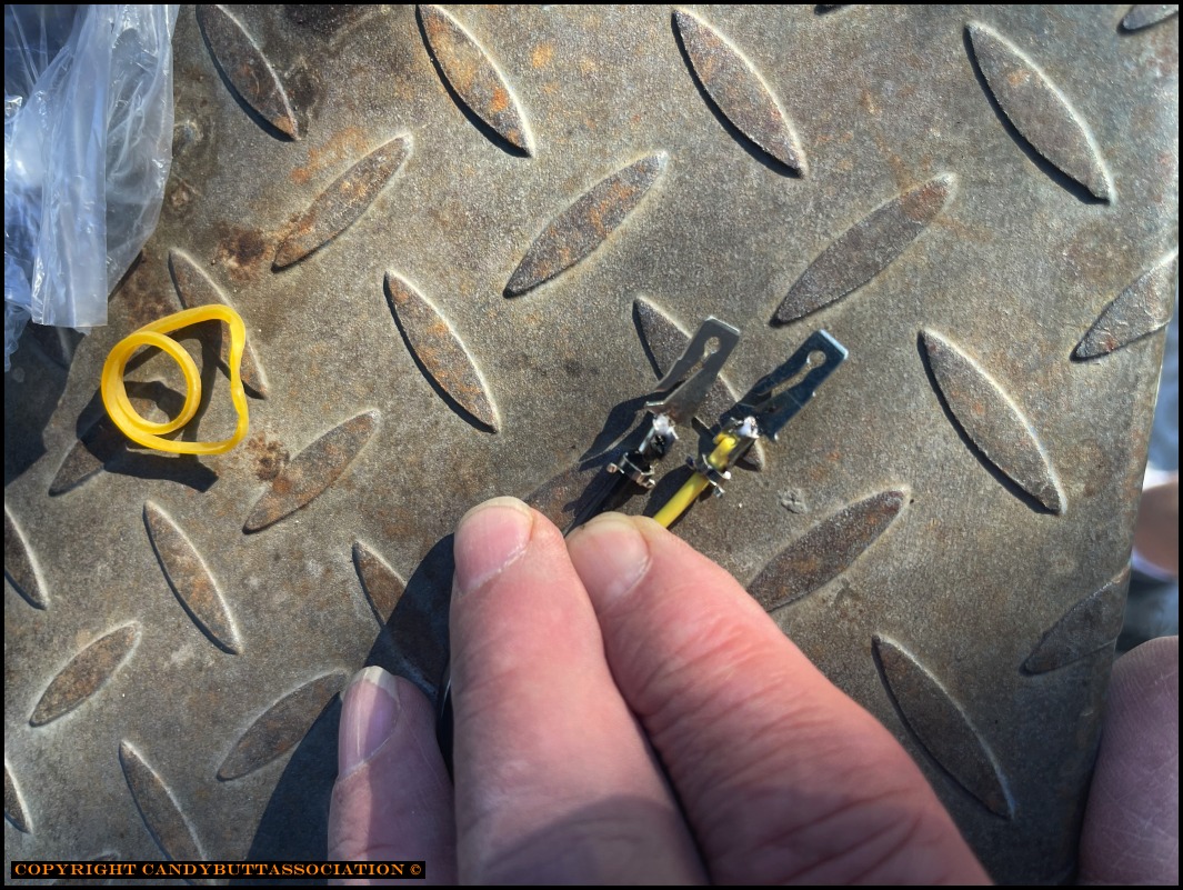
Looks like my next step will be to remove the coils <again>, build a 1 wire to 3 wire splitter (yellow-red from harness) to positive terminal of each coil. Also need to reverse coil connections as they currently (no pun intended!) have Igniter wires on positive terminals.
I've read that coil polarity doesn't really matter... that if reversed the spark will originate from electrode to plug center conductor. But that just seems awkward, LOL.
One last thought. I'm troubleshooting an excessive alternator charging problem on my CBX. Current thinking is voltage drop(s) in the system (key switch, kill switch, connectors, etc) is dragging alternator sense voltage down, fooling the alternator into producing maximum voltage, about 16.5 volts. Your technique might just help me find the voltage drops.
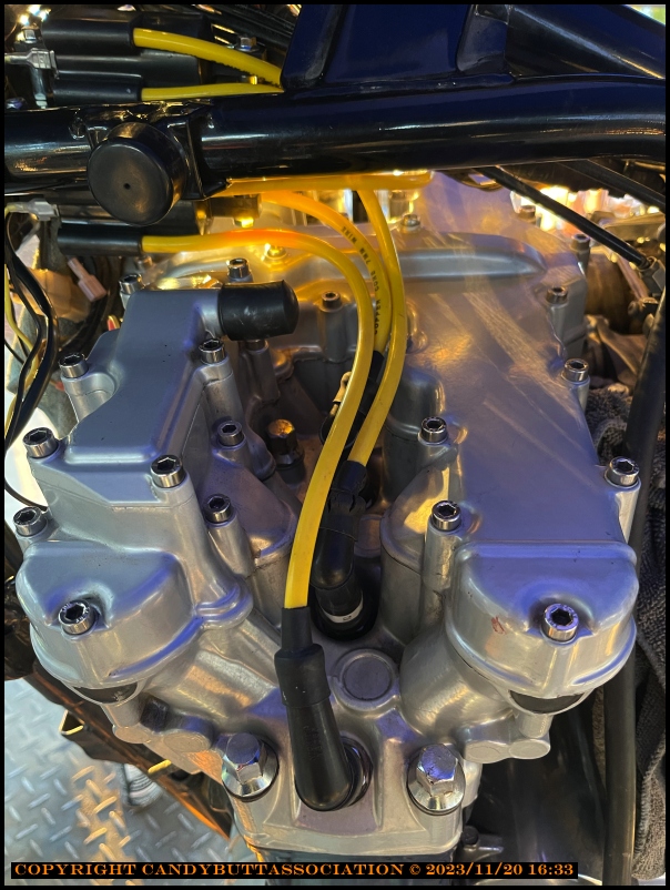
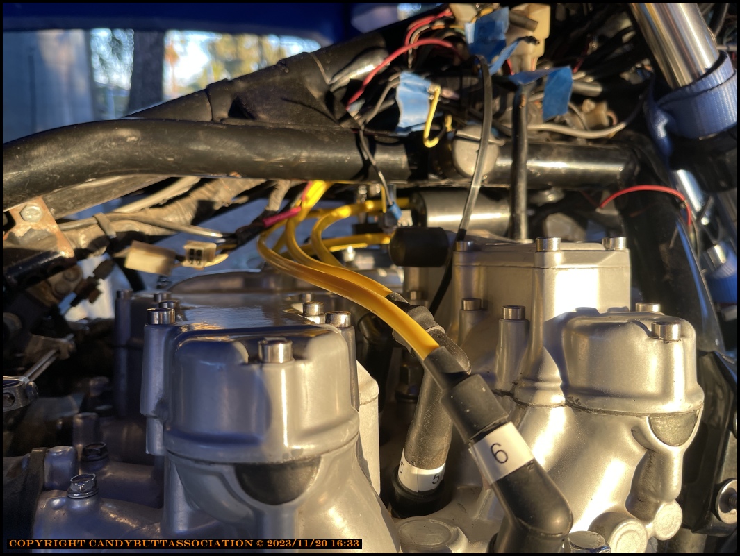
2023-12-12 Great Spark!
Been doing a fan mod. Finally got water in the system meaning I could spin the now-lubricated new mechanical water seal and check for spark.
Removed old plugs, brand new ones laid out across valve cover...
and...
drum roll please,
Beautiful Spark. Strong and Blue, no wimpy yellow half witted sparklers anymore!
2024-03-23 The Coils are from here
Clicky